One of our guidelines when we first dreamt up our virtual robotics environment was to avoid it feeling too much like a game. Instead, our aim was to replicate the sensation of working with tangible, physical hardware. Why? Because we wanted the digital environment to hold the same authenticity as our CodeBot and CodeX curricula.
Let's step back a moment. Our first set of simulated environments, inspired by a school setting, was a true labor of love. Picture this: a classroom transformed with a sprawling line-following track across desks, mimicking a setting that, while possible in the real world, is undoubtedly a tad more cumbersome than in our simulator. That's the ethos behind each challenge we've developed: real-world scenarios that, though feasible, would be difficult but awesome to see in reality. Challenges like climbing a massive wooden structure in the gym (using the accelerometer for navigation), or a dance competition in the auditorium with floating balloons as moving targets. Our “Level-1 Python with Virtual Robotics” mission pack was crafted to provide rigorous Python learning, ensuring learners can start from ground zero and ultimately obtain industry standard Python certifications.
But, innovation doesn't stop at replicating the real. It extends to imagining the fantastic.
That's why we've always been excited about the idea of a haunted house. Picture our CodeBot maneuvering through the gloom, facing challenges that range from eerily realistic to delightfully surreal. This year, we've turned that dream into reality. As Halloween approaches, what better time to introduce our haunted house as a free mission pack?
The haunted house isn't just a fun backdrop; it's a platform for learning and competition. Whether you're diving in solo or representing a team, school, or club, there are fantastic prizes up for grabs. We're talking about winning a physical CodeBot and enticing gift card prizes! Our goal? Simple. Ignite that fiery passion for learning in students, and sometimes, as we all know, a little incentive goes a long way.
The haunted house challenge, while infused with the spirit of Halloween, isn't just a seasonal treat. We intend to keep it available indefinitely. So, even if the thrill of the competition has passed, learners can still face off against the haunted house's challenges, refining their Python skills along the way. Tailored to cater to a wide age group (we believe even ten-year-olds can brave this challenge with no prior coding knowledge), the haunted house truly has "low floors and high ceilings." The Python-powered challenges offer both accessibility for beginners and complexity for the pros. You have the full Python language at your disposal after all! Those with more skills can achieve higher scores.
Eager to embark on this spooky coding journey? For a glimpse of what awaits, do check out our video and delve into the additional links provided.
Until then, happy... and hauntingly fun coding!
Join us, spread the word, and let's make learning Python an unforgettable adventure!
]]>
Two 4' x 8' sheets, 4mm thick white (not opaque) coroplast sign board material
Four PVC pipes: 2” diameter/18” long
One PVC pipe: 3” diameter and cut to fit your tripod base
Three PVC 2” couplings
One PVC adapter: 2” to 4”
16 wooden dowels: 3/8” diameter/2' long
White duct tape
Black electrical tape
Clear packing tape
Painter's tape
Telescopic adjustable tripod stand >8' tall when fully extended (Here's what we purchased from Amazon - Heavy Duty Light Stand)
Short, small bolt and nut (any size will do)
Electric hand held jigsaw with universal fine tooth blade
Dremel Tool
Drill press
Bandsaw or hacksaw
3' rigid ruler/yard stick
Take two sheets of coroplast and cut them in half to make four (4’x4') square pieces.
Stack the four squares and tape them together using painter's tape.
Drill a hole at the end of your yardstick that matches the size of your small nut/bolt combo.
Drill a matching hole, in the EXACT CENTER of the stack of square coroplast pieces.
Drill two more holes in the yardstick (spaced at 14” and 24” from the first hole ).
Pro Tip: Make these two holes smaller. We will be using them to draw the circles we need, using a pencil. Think “spirograph.”
Bolt your fancy spirograph yardstick to the center of the coroplast stack.
Using a pencil and the smaller holes in the yardstick, draw two concentric circles on the top coroplast square.
Remove the yardstick.
Using your jigsaw, cut the outer circle first.
Tape the four circles together using painter's tape.
Drill a starter hole for your jigsaw blade along the inner circle’s outline.
Cut the inner circle.
IMPORTANT: When cutting, be sure to keep all four inner circle cutouts intact. Two of these little donut holes will be used later to create the turn-around areas for the upper and lower platforms. The other two donut holes will be used to create the “shark fin” track adapter to connect the track rings to the track platforms.
Now turn those donuts into track rings by cutting a seam in a VERY straight line as shown in the photo below! .
While using a track ring and a track platform as a guide, draw a “shark fin” shape on a donut hole to join the track to the platform. See photo below for an example. Make two of these “shark fins”, one for each of the platforms.
To allow the tripod to go through the pipes, the dowels need to be inserted into the pipes off-center, close to the edge of the pipe. Space the holes 4 1/2” apart and rotated 90 degrees from each other. The picture below gives you an idea of how the holes should be drilled.
Note how the dowels are positioned off-center to allow the trunk of the tri-pod to pass through the PVC pipes.
Cut 2” diameter PVC pipes down to four 18” pieces. This can be done using a bandsaw, hacksaw, or equivalent.
Use painter’s tape to mark the distances to be drilled.
This step is possibly optional and definitely dependent on the tripod you purchase. The images below will give you an idea of what we are shooting for. The whole objective of this piece is to support the lower platform track piece. You can use a Dremel tool to cut the slots for the tripod base.
This step is also optional, but if you would like your track to be travel friendly (or easily stored in a small place), read on!
Depending on how small you want your track to be will determine how many sections you will need to cut the track rings into. Ideally, it would be best to keep the track rings in their original shape if you have the room to store them, but you can cut them in halves, in quarters, or even in eighths as shown here for maximum portability.
Mark where you will cut each section using a pencil and a ruler. Be careful to make each “slice” of this pie equal in size.
Place painter’s tape between the lines to hold all four rings together.
Cut each slice carefully and be sure to organize the section order for each ring.
While working one ring at a time on a flat surface, tape (using white duct tape) every other, top and bottom track section seam so that each track ring can be folded up like an accordion. Be sure to leave one seam open (not taped).
Now it’s time to put it all together and make one AWESOME track!
Set up your tripod per the manufacturer’s instructions. You may need to replace the plastic wing nuts with smaller standard nuts
If needed, add the custom base PVC pipe you created in Step 3.
Remove all of the tripod’s upper poles leaving only the lower pole attached to the legs.
Make a hole in the center of one of the donut hole cutouts from Step 1 for a snug fit over the tripod’s lower pole. This circular cutout will be used for the track’s lower loopback platform.
Place this platform over the tripod’s pole onto the tripod base.
Replace the remaining tripod poles along with each PVC pipe one at a time.
Connect all four PVC pipes with the three couplings making sure that the dowel holes line up correctly between each pipe.
At the top add the PVC 2” x 4” adapter. This will help support the upper loopback platform.
Add the upper loopback platform.
Insert all 2' wooden dowels in all four PVC pipes.
Position the first track ring on the lower four wooden dowels and use the shark fin adapter to connect the track ring to the lower track platform.
IMPORTANT: Make sure that the CodeBot has enough clearance to drive under the lowest wooden dowel. If more clearance is needed, simply rotate the PVC pipe assembly until just enough clearance is made.
Use white duct tape to attach the track ring to the track adapter and then to the track lower platform.
Use clear packing tape to attach the wooden dowels to the underside of the track ring.
Make the lower loopback line on the shark fin and the lower platform with black electrical tape. See photo below as an example.
Continue up the tripod with the remaining three track rings.
Attach the upper shark fin to the upper platform with white duct tape.
Make the upper loopback line on the shark fin and the upper platform with black electrical tape.
Support the remaining wooden dowels to the underside of the track with clear packing tape as needed.
That’s all there is to it! Time to grab your CodeBot and test out your new Incredible Helix Line Follower Track!
A popular accessory for the CodeBot expansion port is a display. Our OLED Display modules are a great option, and there are instructions at the link below for wiring as well as theory of operation for these bright little displays. Refer to the following post for background, but read on for details of software needed for your CB3: Display Project
]]>
For many teachers, their immediate reaction to the dreaded phrase “Back to School” is something like this famous picture (one of a series, I recently found) by artist Edvard Munch:
Source: The Scream
(If this resonates with you, be sure to check out the full article at https://en.wikipedia.org/wiki/The_Scream)
At Firia Labs, we “get it” (we really do!) and although we couldn’t stop summer from ending, we can at least have your back by offering up our (drumroll please)…
Do you have enough CodeBots and/or CodeX for your expected class size?
Do all the units still have their USB cables?
Do you have enough batteries?
Some kits come with external sensors / speakers / LEDs - are all the parts still there?
To make that last bullet a little more specific - if you have JumpStart and/or Explorer kits, do you still have all of your:
speakers?
thermistors?
light sensors?
alligator clips?
Now that you know what is needed, head on over to firialabs.com and order whatever items were missing when you took inventory.
If you are short on funding, please be sure to check out our Donors Choose Guide and our Grant-Writing Guide.
You should be able to login using the same credentials as before.
If you’re using the new CodeX or Virtual Robotics courses head over to sim.firialabs.com. For these products there is a shiny new License Portal, different from the one you may have used with previous products from Firia Labs.
CodeSpace Development Environment
See the following link for additional help with the new License Portal.
Getting Started with CodeX & Virtual Robotics
If you’re using Jumpstart or Python with Robots, go to make.firialabs.com to login with the same google account you used before. More help on that, and details on handing out share tokens to your class, can be found here.
CodeSpace Licenses & Share Tokens
With your credentials in hand, head on over to the Teacher Dashboard and sign in
Unless you still need the data, you can go ahead and delete any previous classes
This will ensure all of your CodeSpace licenses are freed back up for reuse
Note this does NOT delete any student data or progress.
Next create your new class (or classes)
If you already have your roster(s), you can go ahead and enter your students while you are at it
The engineering team at Firia Labs has had an entire summer to dream up new ideas - there is likely a software update for your products. Rather than tie up valuable classroom time downloading and installing updates into each unit in class, try to set aside some time in advance to do this. This way your students can hit the ground running.
We like to do these over coffee, or while binging on our favorite shows - it’s that easy to do! After you have updated one, it’s just the same process over and over.
Whenever possible, we at Firia Labs watch “real live students”(TM) using our curriculum, and when we notice common stumbling points and patterns, we try to incorporate that back into our curriculum.
So, it’s possible there have been updates to the lessons since you last saw them. Making a quick pass through the lessons will ensure you don’t get stumped by your students in class, plus it will increase your confidence. Besides that, it’s fun telling a computer what to do!
We do the same sort of iterative improvement with our Teacher’s Manuals, so those are worth a fresh look as well.
Can’t locate your Teacher’s Manual? Egads! Contact us at info@firialabs.com and we’ll fix you up.
Rejoin the conversation at the On Fire With Firia group.
For those not familiar with this, On Fire With Firia is a PLN for educators who use CodeSpace to serve as a network for support or for those who want to learn more.
On Fire with Firia Labs (Facebook Group)
Confirm that the plan that you submitted for the 22/23 school year is approved.
If you need to restock your inventory you can order from our website or we can provide you a quote.
Funding concerns can be alleviated. Please be sure to check out our Donors Choose Guide and our Grant-Writing Guide.
In previous years did you use our JumpStart and Explorer kits for your introductory Python classes? If so, head on over to firialabs.com and take a look at CodeX, the new handheld computing platform on the block.
If you’ve tried our Virtual Robotics simulator or have used JumpStart or CodeX and are looking for a “moving experience” in robotics and coding, take a look at the original Firia Labs CodeBots. They’re the inspiration for the robots inside the simulator, and a great step-up in coding challenge from the CodeX and Jumpstart courses.
If industry recognized certifications for Python are an outcome for your students, take a look at our Virtual Robotics learning resources. Virtual Robotics is a good solution for distance learning.
Check out Curt's latest CodeX project!
Use the accelerometer to paint awesome pics on your display.
]]>During Pathfinders summer 2022 week I decided to go through the Python with CodeX Mission 11: Spirit Level to get my feet wet with the latest CodeX firmware and the next generation CodeSpace Development Environment, in order to better assist our teacher students as they experienced the joys of coding in python. I chose this mission because it focused on the accelerometer sensor (which I think is the coolest sensor) and I wanted to build something on top of what was taught in the existing curriculum. But what should I build? I know! How about a 2-axis level? In mission 11 I learned how to find the CodeX tilt angle in the x direction and so it was very easy to include the y direction as well. Okay, now what? The new 2-axis level worked just as I expected but the “bubble” was just an empty circle and hard to see. So to fill in the circle with some color, I went to the CodeX Python module application programming interface (or more simply called the API) help documentation located here - bitmap- Core Graphics Rendering. Hmmmm, rectangles have a color fill function called fill_rect
(x: int, y: int, width: int, height: int, color: int), but to my chagrin, circles do not have a similar color fill function. No problem! I’ll just write the python code myself. Here it is…
for r in range(1, brush_size):
display.fill_circle(x, y, r, color_fill)
By simply drawing concentric circles from 1 to the brush size radius I’m able to fill in a nice looking circle. But there’s a catch! When this bubble circle moves on the screen I need to erase its original position and redraw in its new position. The refresh rate of this erase and draw code is very slow and it doesn’t look very good. It pulses in a very disturbing way so don’t look too long.
I wonder what would happen if I don’t erase the filled bubble circle?
Wow! Now this is a cool effect. I’m actually drawing on this tiny little CodeX monitor! What about writing a simple paint program instead? BINGO! That’s what I’ll do!
Add a color picker control to display all available colors and a clever way to select a fill color.
# U button increases brush size
if buttons.was_pressed(BTN_U):
brush_size += 1
if brush_size > MAX_BRUSH_SIZE:
brush_size = MAX_BRUSH_SIZE
# D button decreases brush size
elif buttons.was_pressed(BTN_D):
brush_size -= 1
if brush_size < MIN_BRUSH_SIZE:
brush_size = MIN_BRUSH_SIZE
Well you don't really "erase" a painting, you just paint over your masterpiece with the background color.
# A button erases with a filled white circle
if (buttons.is_pressed(BTN_A)):
for r in range(1, brush_size):
display.fill_circle(x, y, r, WHITE)
A simple white or black outline around the brush will add the perfect subtle lighter or darker accents.
# B button draws with a filled color circle
elif (buttons.is_pressed(BTN_B)):
for r in range(1, brush_size):
display.fill_circle(x, y, r, color_fill)
display.draw_circle(x, y, brush_size, color_rim)
A button erases
B button draws
A+B buttons toggle black and white outline
L button moves color selector to the left
R button moves color selector to the right
U button increases brush size (max 25)
D button decreases brush size (min 1)
L+R+U+D buttons erase all
from codex import *
from time import sleep
# Constants
CENTER = 120
BK_COLOR = WHITE
MIN_BRUSH_SIZE = 1
MAX_BRUSH_SIZE = 50
SWATCH_LIST = [BLACK, WHITE, RED, GREEN, BLUE, YELLOW, CYAN, MAGENTA,
BROWN, PINK, LIGHT_GRAY, GRAY, ORANGE, DARK_GREEN, DARK_BLUE, PURPLE]
SWATCH_SIZE = int(240 / len(SWATCH_LIST))
FIRST_COLOR = 0
LAST_COLOR = len(SWATCH_LIST)
# Initialize variables
x = CENTER
y = CENTER
brush_size = 15
color_rim = BLACK
color_fill = 0
# Start with a clean white canvas
display.fill(WHITE)
# Function to draw the color picker
def draw_color_picker():
for color in range(FIRST_COLOR, LAST_COLOR):
display.fill_rect(color * SWATCH_SIZE, 0, SWATCH_SIZE, SWATCH_SIZE, color)
display.draw_rect(color * SWATCH_SIZE, 0, SWATCH_SIZE, SWATCH_SIZE, BLACK)
display.fill_rect(color_fill * SWATCH_SIZE, SWATCH_SIZE, SWATCH_SIZE, SWATCH_SIZE, color_fill)
display.draw_rect(color * SWATCH_SIZE, 0, SWATCH_SIZE, SWATCH_SIZE, BLACK)
draw_color_picker()
while True:
# L+R+U+D buttons erase all drawing
if (buttons.is_pressed(BTN_U) and buttons.is_pressed(BTN_D) and
buttons.is_pressed(BTN_L) and buttons.is_pressed(BTN_R)):
display.fill(WHITE)
draw_color_picker()
continue
# U button increases brush size
if buttons.is_pressed(BTN_U):
brush_size += 1
if brush_size > MAX_BRUSH_SIZE:
brush_size = MAX_BRUSH_SIZE
# D button decreases brush size
elif buttons.is_pressed(BTN_D):
brush_size -= 1
if brush_size < MIN_BRUSH_SIZE:
brush_size = MIN_BRUSH_SIZE
# L button moves color selector to the left
if buttons.was_pressed(BTN_L):
# Erase the previous color selector
display.fill_rect(color_fill * SWATCH_SIZE, SWATCH_SIZE, SWATCH_SIZE, SWATCH_SIZE, WHITE)
display.draw_rect(color_fill * SWATCH_SIZE, SWATCH_SIZE, SWATCH_SIZE, SWATCH_SIZE, WHITE)
# Move color selector one position to the left
color_fill = color_fill - 1
# Wrap around to last position if on the far left
if color_fill < FIRST_COLOR:
color_fill = LAST_COLOR - 1
# Draw the filled color rectangle with a black border
display.fill_rect(color_fill * SWATCH_SIZE, SWATCH_SIZE, SWATCH_SIZE, SWATCH_SIZE, color_fill)
display.draw_rect(color_fill * SWATCH_SIZE, SWATCH_SIZE, SWATCH_SIZE, SWATCH_SIZE, BLACK)
# R button moves color selector to the right
if buttons.was_pressed(BTN_R):
# Erase the previous color selector
display.fill_rect(color_fill * SWATCH_SIZE, SWATCH_SIZE, SWATCH_SIZE, SWATCH_SIZE, WHITE)
display.draw_rect(color_fill * SWATCH_SIZE, SWATCH_SIZE, SWATCH_SIZE, SWATCH_SIZE, WHITE)
# Move color selector one position to the left
color_fill = color_fill + 1
# Wrap around to the first position if on the far right
if color_fill > LAST_COLOR - 1:
color_fill = FIRST_COLOR
# Draw the filled color rectangle with a black border
display.fill_rect(color_fill * SWATCH_SIZE, SWATCH_SIZE, SWATCH_SIZE, SWATCH_SIZE, color_fill)
display.draw_rect(color_fill * SWATCH_SIZE, SWATCH_SIZE, SWATCH_SIZE, SWATCH_SIZE, BLACK)
# Read the accelerometer sensor and get its raw values and convert to degrees in X and Y
# From Python with CodeX Mission 11: Spirit Level
val = accel.read()
tilt_x = val[0]
tilt_y = val[1]
scaled_x = (tilt_x / 16384) * 90
scaled_y = (tilt_y / 16384) * 90
degrees_x = int(scaled_x)
degrees_y = int(scaled_y)
# Clamp the X angle to -90 an +90
if degrees_x < -90:
degrees_x = -90
elif degrees_x > 90:
degrees_x = 90
# Clamp the Y angle to -90 an +90
if degrees_y < -90:
degrees_y = -90
elif degrees_y > 90:
degrees_y = 90
# Set the new brush center with X/Y tilt angles
x = CENTER + degrees_x
y = CENTER + degrees_y
# A+B buttons toggle black and white outline
if (buttons.is_pressed(BTN_A) and buttons.is_pressed(BTN_B)):
if color_rim == WHITE:
color_rim = BLACK
else:
color_rim = WHITE
# A button erases with a filled white circle
if (buttons.is_pressed(BTN_A)):
for r in range(1, brush_size):
display.fill_circle(x, y, r, WHITE)
# B button draws with a filled color circle
elif (buttons.is_pressed(BTN_B)):
for r in range(1, brush_size):
display.fill_circle(x, y, r, color_fill)
display.draw_circle(x, y, brush_size, color_rim)
Upload the code to your CodeX and make some of your own amazing art! If you have an idea of how to improve the Wet Paint app, then step through the code with CodeSpace’s built-in debugger to better understand what’s going on and write your Python code into reality! Be sure to share your new found creativity in the arts and sciences, and most importantly, have fun!
You can download the complete code from our public repository at https://bitbucket.org/firia/labs-demos/src/master/codex/wet_paint_app/.
]]>As a nerdy Software Engineer, I could try and present logical reasonsTM why you should attend one of Firia Labs Professional Development (PD) opportunities. Instead, I’m going to do something out of character and talk about feelings…
Specifically, how I suspect you will feel at the various stages of your Professional Development Journey.
Stage 1 - Apprehension
Over the years at Firia Labs, we’ve seen a lot of what we’ve dubbed “Computer Science Draftees” - librarians, coaches, science teachers and math teachers who don’t know coding at all who somehow got tapped to teach an upcoming Python coding class at their school.
Sometimes they do have some exposure to coding, but only in the form of drag-and-drop programming (AKA “blocks”).
Even in the best case scenarios, it’s often true that a CS teacher knows some other text-based programming languages (JAVA, C++, etc.) but has not yet been exposed to Python.
If any of these scenarios describes you, you may be feeling a sense of dread at the thought of teaching something you don’t know.
Stage 2 - Longing
Since staying stuck in stage 1 forever isn’t any fun, you’ll probably then enter a “searching” mode, trying to find some resources (anything!) that can help.
Hopefully that’s how you came to find this blog post, and I also hope that you have run across one or more descriptions of our upcoming PD Opportunities.
So the next stage in your journey is to get signed up, and you move to…
Stage 3 - Skepticism
There’s probably no way around this stage… until the date of the training actually arrives, what could convince you otherwise?
However, time marches on, and soon you will be at your first day of PD, leading to…
Stage 4 - Relaxation
As the PD session gets rolling, seeing the first few examples of how truly easy to use the CodeSpaceTM
learning environment is will start melting away the dread and apprehension you experienced in stage 1.
As you work through more and more coding exercises (led by one of our wacky instructors), your pleasant, calm emotional state is going to be replaced by…
Stage 5 - Excitement
We’ve seen it time and again - as the teachers work through more and more of the lessons, and see how integrated features like the Python Debugger and the ToolBox (a built-in Reference Guide) make it easier to get unstuck, attendees start feeling energized and begin looking forward to sharing the coding lessons with their students.
After the PD session, you hit the best stage of all…
Stage 6 - Confidence
After you have completed one of Firia Labs PD sessions, you will feel confident in your ability to help your students learn Python Coding.
Reaching this stage is the goal of your PD Journey, and why I encourage you to take advantage of such an opportunity when it presents itself.
]]>
In the first blog of this two-part series, we built a cool pair of NeoPixel glasses that are powered by your CodeX. Now that the hardware is complete, we get to the fun part: the software! In this blog, we will code up some cool, flashy animations for the CodeX glasses.
Your CodeX has four NeoPixels built-in. The CodeX python library has built-in support for these LEDs, and you can use the same library to control your own added pixels. The built-in NeoPixels are those little white boxes labeled “RGB” in the upper left and upper right corners of the CodeX.
Each NeoPixel contains three LEDs (red, green, and blue) and a driver chip that reads serial data and lights them up. Each pixel has a single input wire. You control the pixels by sending 24 bits of serial data on this wire. That’s 8 bits (one byte) for red, 8 bits for green, and 8 for blue. The higher the values you send, the brighter the individual LEDs will be. The value 0 is off while a value of 255 is full on. Thus a 24 bit value of (255, 255, 255) is full-red plus full-green plus full-blue. which makes white. Warning: NeoPixels can get very bright!
Each pixel also has a single output wire that can be connected to the input wire of another pixel. When the first pixel has read its 24 bits of data, it passes any subsequent bits to the next pixel. When this second pixel has read its data, it passes the remaining bits on to the next pixel and so on down the line.
Let’s say you have a chain of 20 pixels you want to light up. First, you build a list of 20 Red/Green/Blue values – one set of three values for each pixel. Now you grab the input line of the the first pixel and rapidly stuff all three bytes down the wire one bit at a time. Next, you get the 2nd pixel’s values from your list and stuff those bits down the wire -- followed by the 3rd pixel’s RGB values and so on until you have crammed all 20 sets of values down that one tiny wire.
The bits go out quickly, and the timing is critical. Fortunately, the CodeX library does all the timing for you. All you have to do is make a regular old list of values in Python and pass it to the library for processing.
Want to learn more about NeoPixels? Check out the Adafruit guide to all-things NeoPixel.
You can attach a chain of neopixels to each of the four peripheral connectors on the CodeX. These connectors are on the bottom of the board in the upper left and upper right corners.
The pins of each connector are labeled on the CodeX circuit board. The “G” is the ground pin. The “S” is the signal pin (where you send the data bits). The unlabeled center pin is the 5V pin to power your pixel strip.
First, your code needs to configure a neopixel object to talk to your strip of pixels:
import board
import codex
import neopixel
import time
import random
codex.power.enable_periph_vcc(True)
# IO13 = EXP0
# IO14 = EXP1
# IO10 = EXP2
# IO11 = EXP3
# Glasses are 'GRB' with 2 rings of 24 (total of 48)
neo = neopixel.NeoPixel(board.IO13, 48, pixel_order='GRB', auto_write=False)
neo[0] = (100,0,0)
neo[1] = (0,100,0)
neo[2] = (0,0,100)
neo.show()
time.sleep
Line 7 above is very important! This tells the CodeX board to supply power on the 5V pins of the peripheral connectors. By default, the power output is turned off. It is up to you to turn the power on, and if you don’t the pixels won’t light up. I’ve pulled out many a gray hair debugging pixels when I forgot this line of code. Save your hair; remember this line!
Line 15 builds a NeoPixel object to talk to the external pixel strip. You must pass in a few pieces of information to tell the library about your pixel strip. First, you tell the library which peripheral port you want it to use. In the last blog post, we connected the glasses to peripheral port 0. That signal wire is CodeX’s board.IO13
GPIO pin.If you are using another peripheral port, use the proper GPIO pins as shown in the comments on lines 9 through 12.
Next, you tell the NeoPixel library how many pixels are on your strip. Our glasses are two rings of 24 for a total of 48 pixels.
Next, you tell the library what order the data bits must be sent in. Our pixel rings expect green data followed by red data followed by blue. That’s the pixel_order='GRB'
on line 15. If your neopixels have a different order, you will need to swap the ‘RGB’ around.
Finally, we tell the library not to automatically update the pixel strip with every change we make: auto_write=False
. The library keeps up with the states of all the pixels it controls. Its default behavior (auto_write = True) is to redraw the entire chain every time you change a single pixel. But we want to make several changes to the data and only redraw the strip when we are done.
The neopixel library gives us back an object with an internal list to hold all the pixel values. We access the pixel values as we would access the elements of a regular old python list – with the brackets. Lines 17, 18, and 19 write color values to the first three pixels. Pixel 0 gets red=100. Pixel 1 gets green=100, and Pixel 2 gets blue=100. Remember, values can be from 0 to 255.
Nothing actually happens to the strip until we call neo.show()
on our library object. That tells the library to redraw the pixel chain. Once it is redrawn, we can make other changes to the pixel buffer. But the changes won’t be seen until the next neo.show()
call.
Finally, there is a 5 second sleep at the end of the program. This is very important too! As soon as your program ends, the CodeX turns the peripheral power back off, and all the pixels will go dark. We’ll keep the program alive (but asleep) for a few seconds so we can see the pixels. We won’t need this sleep in our final code. Our final code will never end; it will run forever flashing the pixels on the glasses.
Now for our first animation sequence! I call it “sparkle”. One cool part of creating code is naming all the things! The “Sparkle” sequence assigns a random color to each of the 48 pixels 10 times a second. The pixels appear to, well, sparkle.
This sequence is easy:
import board
import codex
import neopixel
import time
import random
codex.power.enable_periph_vcc(True)
neo = neopixel.NeoPixel(board.IO13, 48, pixel_order='GRB',auto_write=False)
def rand_color():
return (random.randrange(0,11),random.randrange(0,11),random.randrange(0,11))
def sparkle(num):
for _ in range(num):
for i in range(48):
neo[i] = rand_color()
neo.show()
time.sleep(.1)
while True:
sparkle(40)
Lines 1 through 8 are our setup code from before.
On line 10, I’ve defined a function to return a random RGB color. This is a useful function we’ll use a lot in the code to come, so it is good to factor it into a reusable helper function. I have limited the range of each color component to 0-10, which is plenty bright and helps save battery power.
Line 13 is the sparkle function. This function takes the number of “loops” you want it to make. Each loop is a bit longer than a tenth of a second (it takes time to build the data and shift it out). Later, when we have lots of animations, we can pass in how long the “sparkle” function runs before another animation takes over.
Line 20 and 21 are our main loop. Right now we only have one animation, and we call it over and over.
This is the general pattern of our code. We’ll add new animations as functions that get called from our main loop. Now let’s make some more animations! Any ideas?
The “pulse” animation works like a dimmer switch. The glasses are set to a random color and the dimmer switch goes up and down to “pulse” all the pixels to that color. All the pixels get brighter then dimmer, but all at the same color.
def pulse(num):
color = [0,0,0]
rc = random.randrange(0,3)
for _ in range(num):
for i in range(10):
color[rc] = i
for t in range(48):
neo[t] = color
neo.show()
time.sleep(.05)
for i in range(9,-1,-1):
color[rc] = i
for t in range(48):
neo[t] = color
neo.show()
time.sleep(.05)
while True:
sparkle(40)
pulse(4)
I am only showing the new lines code from now on. The code in your editor will grow as we add more and more functions.
Just like the sparkle function, the pulse function takes the number of cycles. A cycle is the LEDs going from off to full color and back down to off. The loop at line 4 counts the cycles. Note the variable “_”. You can call it anything you like, but since we aren’t using it anywhere, I like to call it “_”.
On line 3 we pick an LED to brighten/dim … 0 (red), 1 (green), or 2 (blue).
The loop at line 5 steps the brightness of the given LEDs from 0 to 10 (our full value).
The loop at line 11 steps the brightness of the given LEDs from 10 back to 0.
And I added the call to the main loop at line 20. Now our glasses sparkle for a few seconds, pulse a random color 4 times, and repeat over and over.
Woo hoo! These glasses are already impressive, but we can add more. Any ideas yet? What’s next?
I really want to do some true “animations” where pixels are moving around the glasses. Imagine a single pixel revolving around the lenses in a side-ways figure-8 (the symbol for infinity). If you are facing the glasses, you’ll see the pixel start at the nose on the right lens and move clockwise around the lens back to the nose. Then the pixel jumps over the the nose and goes counter-clockwise around the left lens. And then it jumps back over to the right lens in a continuous loop.
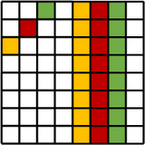
I could make this animation easier by totally rewiring the glasses as shown below:
The red letters are the existing wiring configuration. When I turn on neo[0]
I am controlling the pixel near the top of the right lens shown by the red number “0”. I would rather rotate that first pixel around to where the red number “18” is. And I could have glued the left ring in that position. But there is no way I could rotate the right lens to get the counter-clockwise orientation. (Give it a try in your mind).
Instead, I’m going to make a mapping function so that my code can pretend the pixels are laid out like the blue numbers. But then the mapping function moves the data in the array around to match the physical layout shown by the red numbers.
I can use an array to define which pixel moves to where. Like this:
MAP_INFINITY = [
6, 7, 8, 9,10,11,12,13,14,15,16,17,18,19,20,21,22,23, 0, 1, 2, 3, 4, 5,
29,28,27,26,25,24,47,46,45,44,43,42,41,40,39,38,37,36,35,34,33,32,31,30
]
def do_map(data,dst,map):
i = 0
while i<48:
dst[i] = data[map[i]]
i += 1
The mapping array is defined on line 1. The actual mapping function is on line 6. The function takes data
, which is our input source data (the pretend blue-number mapping above). The dst
is the output array to populate (the physical red-number mapping above). We’ll just pass in the neopixel library object and let the function write straight to it. The map
is the mapping array that lists where a physical pixel’s data is located in the input data
. We only have one mapping now, but we can define others later (hint).
Have a look at the numbers in MAP_INFINITY
. Starting with physical pixel "0", the data comes from our source array "6". Physical pixel "1" comes from the source array at index "7" and so on up to the last physical pixel "47" which comes from our source array at index "30". Check in our picture. The blue number "47" matches up with the red letter "30".
def infinity(num):
for _ in range(num):
for i in range(48):
d = [(0,0,0)]*48
d[i] = (10,10,10)
do_map(d,neo,MAP_INFINITY)
neo.show()
while True:
infinity(10)
sparkle(40)
pulse(4)
Once again, only the new things from the code are shown.
The “infinity” animation function takes an argument – the number of loops around the glasses you want the single pixel to make.
The loop on line 3 walks the pixel around all glasses from pixel 0 to pixel 47. Line 4 creates a new pixel list with all 48 LEDs off. Then line 5 sets the one target pixel to white.
Line 6 maps the source array onto the neo pixel map, and line 7 shows the pixels.
On line 10, our main loop adds the infinity animation.
See how easy the animation is once we have the pixels in a straight line in the proper order?
Some animation ideas I have show the same pixel patterns on both lenses – copies of each other. We can use mapping functions to make these copies and mirror images of the lenses.
How about this mapping function:
Whatever you draw on the right lens is duplicated on the left lens, but mirrored on the left lens’s X axis.
Maybe a straight copy with no flipping at all:
Or maybe mirrored on the Y axis instead of the X:
Or maybe mirrored on both the X and Y axis (just to complete all flip possibilities):
Just like with the “infinity” map, we can build mapping arrays to pass to our “do_map” function. Here they are:
MAP_INFINITY = [
6, 7, 8, 9,10,11,12,13,14,15,16,17,18,19,20,21,22,23, 0, 1, 2, 3, 4, 5,
29,28,27,26,25,24,47,46,45,44,43,42,41,40,39,38,37,36,35,34,33,32,31,30
]
MAP_COPY = [
6, 7, 8, 9,10,11,12,13,14,15,16,17,18,19,20,21,22,23, 0, 1, 2, 3, 4, 5,
6, 7, 8, 9,10,11,12,13,14,15,16,17,18,19,20,21,22,23, 0, 1, 2, 3, 4, 5,
]
MAP_COPY_FLIP_X = [
6, 7, 8, 9,10,11,12,13,14,15,16,17,18,19,20,21,22,23, 0, 1, 2, 3, 4, 5,
5, 4, 3, 2, 1, 0,23,22,21,20,19,18,17,16,15,14,13,12,11,10, 9, 8, 7, 6,
]
MAP_COPY_FLIP_Y = [
6, 7, 8, 9,10,11,12,13,14,15,16,17,18,19,20,21,22,23, 0, 1, 2, 3, 4, 5,
17,16,15,14,13,12,11,10,9, 8, 7, 6, 5, 4, 3, 2, 1, 0,23,22,21,20,19,18
]
MAP_COPY_FLIP_XY = [
6, 7, 8, 9,10,11,12,13,14,15,16,17,18,19,20,21,22,23, 0, 1, 2, 3, 4, 5,
18,19,20,21,22,23, 0, 1, 2, 3, 4, 5, 6, 7, 8, 9,10,11,12,13,14,15,16,17
]
The “wipe” animation completely fills the lenses with a single color. The wipe begins at index 0 and spreads to index 1, 2, 3, and so on up to index 23. The left lens will be a copy of the right using whatever mapping function you want from the list above.
def wipe(color,map,reps):
buffer = [color]*24
for _ in range(reps):
color = rand_color()
for i in range(24):
buffer[i] = color
do_map(buffer,neo,map)
neo.show()
time.sleep(.05)
return color
while True:
infinity(10)
sparkle(40)
pulse(4)
last_color=(0,0,0)
last_color=wipe(last_color,MAP_COPY,2)
last_color=wipe(last_color,MAP_COPY_FLIP_X,2)
last_color=wipe(last_color,MAP_COPY_FLIP_Y,2)
last_color=wipe(last_color,MAP_COPY_FLIP_XY,2)
The wipe function takes the parameter “color”, which is the background color of the glasses. The “map” is the mirror mapping you want to use. And “reps” is the number of wipes to make – the number of loops just like the other animation functions take.
Line 2 builds the initial buffer with the background color. On line 4 we pick a new random color to fill with. The loop at line 5 sweeps over the array pixel by pixel and sets the new color.
Line 10 returns the random color that the function picked. This allows the main loop to pass this color as the background for another wipe. On line 16 of the main loop, we start with the color “black”. Each call to wipe passes in the return from the previous wipe.
Fancy eh?
OK. This next animation is my favorite! First, the code draws a pattern of 4-2-4-2-4-2-4-2 pixels on the mirrored lenses (see below). The “2” pixel pairs are black. Each “4” pixel pattern has a single random color.
Each step of the animation pulls the first pixel off of the beginning of the list and appends it to the end. The effect is a continuous rotating wheel on the lens. And I mirror the right lens onto the left so they “turn” in opposite directions.
def wheel(num):
color1 = rand_color()
color2 = rand_color()
color3 = rand_color()
color4 = rand_color()
buffer = [0] * 24
for i in range(4):
buffer[i]= color1
buffer[i+6] = color2
buffer[i+12] = color3
buffer[i+18] = color4
for _ in range(num):
do_map(buffer,neo,MAP_COPY_FLIP_X)
neo.show()
time.sleep(0.1)
a = buffer[0]
buffer = buffer[1:]
buffer.append(a)
while True:
wheel(48)
infinity(10)
sparkle(40)
pulse(4)
last_color=(0,0,0)
last_color=wipe(last_color,MAP_COPY,2)
last_color=wipe(last_color,MAP_COPY_FLIP_X,2)
last_color=wipe(last_color,MAP_COPY_FLIP_Y,2)
last_color=wipe(last_color,MAP_COPY_FLIP_XY,2)
Lines 2 through 4 pick four random colors for the wheel. Line 6 starts the buffer with all pixels black.
The loop at line 7 adds the 4 colored “spokes” to the wheel.
Line 12 is the rolling loop. First it shows the wheel and pauses for a 10th of a second. Then line 16 gets the pixel value from the front of the list (index 0). Line 17 slices this first element off the front of the list and line 18 appends that element to the end.
What cool ideas do you have for animations on the glasses? I am excited to see what you come up with! Email me your code and we’ll share your awesome work with the rest of the CodeX community.
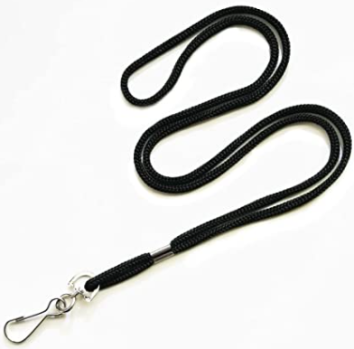
I’ve been thinking about a GUI to select my animations from the CodeX display screen. If I wear the CodeX on a lanyard around my neck, I can use the buttons to navigate the list of animations on the screen and pick the ones I want to show. Let me know if you have GUI ideas!
You can download the complete code from our public repository at https://bitbucket.org/firia/labs-demos/src/master/codex/neopixel_glasses/.
]]>Wearable LEDs are all the rage! Do a quick search on Pinterest and Etsy and you’ll find oodles of wearable flashy-light projects – from simple jewelry to full LED-infused dresses and jackets. In this two-part blog, I’ll show you how to use your CodeX to control a pair of sparkling NeoPixel glasses. Imagine how cool you’ll look at that next party or robotics competition with sparkly LED rims flashing in animated patterns that you program!
The CodeX has four peripheral expansion plugs – two in the upper left and two in the upper right. You can use these expansion ports to control all kinds of add-on hardware including sensors, servos, and yes: NeoPixels.
NeoPixel strips need three wires: 5V power, ground, and the serial signal input. Each of the CodeX plugs has these three wires ready to go! Flip the CodeX over and look closely at the four plugs along the top:
The ground
and signal
pins are labeled with ‘G' and 'S’. The center pin is the 5V voltage
to drive the pixels.
You have the CodeX. Now let's gather the parts to make the glasses!
Part | Description | Suggested Cost |
Suggested Source |
Two 24-pixel Neopixel rings. |
$10 * 2 |
LED Ring Lamp Light
|
|
Plastic costume glasses with no lenses. Find these at your local party store or costume shop. | $10 | ||
3 wire (or more) cable to run from glasses to the CodeX. Audio cables or USB cables are perfect. Look for 10-foot cables. | $11 | ||
3 female jumper wires to plug into CodeX. If you don’t have any on hand, get yourself an assortment for later use. | $6 (for assortment) | ||
If you don’t already have a soldering iron, get yourself a kit that includes everything you need. This suggested kit is perfect for light soldering work. | $10 | Soldering Kit | |
You need glue to hold the lenses (and wires) in place. Five-minute epoxy or super-glue is perfect. | $10 | Gorilla Epoxy |
Part | Description | Suggested Cost | Suggested Source |
Instead of jumper wires, you might use an official latching connector at the CodeX. Get yourself a few of these for future CodeX expansion projects! | $2 | Cable Assembly | |
If you want to wear the CodeX around your neck, you’ll need a lanyard. Of course string or yarn works just fine too! | $6 (for 10) | Lanyard | |
You can use a knife and scissors to cut/strip wire. But do yourself a favor – get an official tool. You’ll find all kinds of options at your local home-improvement store. | $7 | Wire Stripper & Cutter |
A few years ago, Adafruit published a guide on making New Year’s Eve “Celebration Spectacles” with NeoPixel rings. Have a look at their guide (and video) before diving into our CodeX version: Celebration Spectacles.
First, we need to glue the NeoPixel rings to the plastic glasses. We will be making animations that cross both rings, so it is important to mount the rings in a known position. That way our code knows exactly where each of the 48 pixels is located in space.
Find the two solder holes labeled “IN” and “OUT” on your NeoPixel rings. Rotate each ring until these holes are at the top. The pixels at the top of each ring between these labels are the first (pixel 0) and last (pixel 23) pixels in the chain.
Glue both rings to the plastic frame with the first and last pixels at the top. Five minute epoxy is plenty strong and gives you a moment to adjust the placement of the rings before the glue sets. Pay attention to the four pixels at the bridge of the glasses where your nose will be. Our animations will cross the bridge of the glasses at these four pixels. Make sure they are aligned across from each other:
Now for the cable between the glasses and the CodeX. Decide how long you want the cable to be. I wear my CodeX around my neck so I can control the animations with the CodeX’s buttons. Three or four feet is plenty long enough. Another option is to put the CodeX in your pocket and run the cable under your shirt. You’ll need a four or five foot cable for that. A five foot cable gives you plenty of options, but you might end up with a dangling cable if you wear the CodeX around your neck!
Add an extra foot to your desired length and cut the cable. Carefully strip the outer layers from the extra foot of the cable. Strip a couple of inches from the other end (see photo below). Take your time with this step. Be careful not to nick the insulation on the individual wires. Finally, wrap some scotch tape around the ends to keep the braid from unraveling.
Cut the long exposed wires in half (6 inches). This gives you three wires to connect the two rings together.
Each ring has two PWR
and two GND
holes. Run a wire between a PWR
and GND
between the rings. Carefully measure the wires so they fit perfectly when wrapped around the inside of the frame. That way they are out of sight. As you are looking at the back of the glasses, wire the DOUT
from the left ring (the one that will be closest to your left ear) to the DIN
of the right ring.
Use a few tiny drops of glue to secure the wires against the frame.
Now tape the long-wire-end of the cable about halfway down the left arm of the glasses (see the photo below). Again, cut the long wires to the perfect length so you can hide them around the frame of the glasses and out of sight. Use tiny drops of glue to secure the wires against the frame.
Carefully note which color wire from the cable is soldered to which solder pad on the ring.
Finally, add the CodeX connector to the free end of the cable. Cut three of your female connector wires and solder them to the cable wires (see photo below). Straighten each wire into a line and wrap the bare metal solder joints with electrical tape to keep the wires from shorting together. Or better yet, use shrink tubing and a heat gun (or a match). You can see my shrink tubing on the wires in the photo below. I’ll slide those tubes down over the solder joints and heat them to shrink them firmly in place.
Pick a color code you can remember. I use a red female jumper for PWR
, black for GND
and blue or green for DIN
. When you plug these jumpers into the CodeX, the red wire goes in the middle pin. The blue wire DIN
goes to the signal pin “S”, and the black wire GND
goes to the “G” pin.
Here is another pair of glasses with a latching connector instead of 3 jumper wires:
And now for the moment of truth! Connect your glasses to the CodeX peripheral port 0 (EXP0) and run the following test program. If your wiring is right, you’ll see all the pixels light up and twinkle with a random color!
If they don’t light up, then turn the CodeX off and carefully check your wiring. Make sure all the solder joints are good. Follow each wire color to make sure the CodeX pins end up at the right solder pads on the rings. Make sure the CodeX “S” wire connects to the first ring’s DIN
and that DOUT
of the first ring goes to DIN
of the second ring.
import board
import codex
import neopixel
import time
import random
codex.power.enable_periph_vcc(True)
# IO13 = EXP0
# IO14 = EXP1
# IO10 = EXP2
# IO11 = EXP3
# Glasses are 'GRB' with 2 rings of 24 (total of 48)
neo = neopixel.NeoPixel(board.IO13, 48, pixel_order='GRB')
while True:
for i in range(48):
# values from 0 to 255, but this saves power (and isn't blinding)
neo[i] = (random.randint(0,32),random.randint(0,32),random.randint(0,32))
time.sleep(0.1)
Congratulations! Your pixels are flashing! Parade around the house with your glasses on for all to see. While you are in the kitchen, grab yourself a soda and a snack to celebrate!
Oh, and now is a good time to clean up your desk. Look at all those scraps of wire and snippets of insulation and used tape. Are those solder blobs on the table? Those should scrape right up. And how about we put all those tools away before someone gets hurt on them? Heck, I sound like your mother.
In the next blog post, we’ll write the code to control those 48 pixels. That’s when the real fun begins.
]]>
The CodeBot has thirteen visible LEDs you can turn on and off with your Python code. You already know that – you’ve been through the awesome Python with Robots lessons to blink each of those. But if you are like me, you are thinking, “I need more LEDs!” Thirteen isn’t nearly enough. It’s not even close.
In this blog post I’ll show you how to connect a whopping 128 LEDs to the CodeBot with just four wires! And with a few lines of Python code, we’ll bring those LEDs to life.
Along the way, you’ll learn about I2C (pronounced “eye-squared-see”) and about talking to real life hardware devices. You’ll also learn some valuable experimenting techniques – how to tinker to answer the big questions like “how does this thing work?” You are the detective, and this little 8x8 LED matrix is your mystery device. Let’s snoop around under the covers and see what it can do!
I used the 8x8 bi-color display matrix from Adafruit. Each of the 64 display elements is made from two LEDs – a red and a green. You can turn each on individually or turn them both on to make yellow (actually, it looks more like orange to me!)
Let’s do some math. That’s 8 * 8 elements * 2 LEDs each = 64 * 2 = 128 LEDs total.
I must warn you. Rather, I must excite you: if you buy one of these displays, some assembly is required. You have to … I mean you get to have the fun of … soldering the display to the circuit board. It’s super easy to do, and it is the perfect first soldering project if you’ve never soldered. You can buy a simple soldering kit with everything you need for less money than the display itself. For instance: https://www.amazon.com/Soldering-Iron-Kit-Temperature-Rarlight/dp/B07PDK3MX1.
Adafruit has a great “how to” page on this display showing you how to put it together, check it out here.
If you are a beginner, you can watch YouTube tutorials to get started with soldering. Or you can seek out a local “makerspace” in your hometown. The folks there will be eager to assist. Or heck, swing by our office here at Firia Labs and we’ll help you put your display together.
The I2C bus is a simple way for a microprocessor to talk to low speed hardware devices. Data is sent back and forth on the bus serially (one bit at a time) with just two wires: a data line and a clock line.
Multiple devices can be attached to the same two-wire bus. Each device must have its own unique seven-bit address (0 - 127). The microprocessor talks to a device by first sending the address on the bus followed by one or more bytes of data. All the devices on the bus see the communication, but only the device with the target address reacts.
With so many chip makers and so many types of I2C devices, there are bound to be address conflicts. How do you connect two devices that have the same address? How do you connect three of these 8x8 displays at the same time if they all have the same address?
Most I2C devices allow you to select a different address by connecting one of the chip’s pins to high or low voltage. The Adafruit 8x8 display has three such pins, and you can change the address with three solder pads on the back of the display board. The Adafruit learning guide referenced above goes into great detail. Basically, you drop a blob of solder across the square pads to configure the desired address.
You see that chip with all the legs on the back of the board? That the HT16K33 chip. It is a generic I2C-LED driver chip made by Holtek that can be used in a variety of applications. Adafruit makes several display boards that use this same driver chip. We’ll explore more of them in a future blog post.
Place your handy Firia CodeBot Expansion Module onto your CodeBot. Place the four pins of the display somewhere on the top half of the board like you see in the image below. Leave a row or two at the top of the display to plug in the wires.
You’ll need four wires to connect the display board to your CodeBot. The four pins of the display are labeled at the top of the board. Connect “+” on the display board to the expansion connector’s “3.3V” plug. Notice there are TWO plugs labeled “3.3V”. Actually, there are two of everything – one on each side of the board. Both sides are wired together, and you can use either side for any signal.
Connect the “-” on the board to the expansion’s “GND” plug. The “C” on the display board is the “clock”. Connect it to “SCL” on the expansion. Finally, connect the “D” on the display board (“data”) to the “SDA” plug on the expansion. And that’s it!
You can jump right onto the CodeBot’s I2C bus using the Python REPL. You can send bytes on the I2C bus right there from the command line and experiment with the display live and in person.
Connect your CodeBot and open CodeSpace in your browser. Select “Show Debug Panel” from the “View” menu. Then select “Show Advanced Debug Panel” from the “View” menu. You’ll see the REPL window in the lower left hand corner of the CodeSpace page.
Enter some commands to get the Python juices flowing:
The CodeBot uses its I2C bus to talk to its accelerometer. You remember working with “botcore.accel” in the CodeBot lessons. Remember, you checked the accelerometer for movement and made an alarm. The “botcore.accel” has an I2C object it uses to talk to the bus. You can borrow that module’s object for your own use (it won’t mind).
Here is how to do it:
>>> from botcore import *
>>> i2c = accel.i2c
>>>
>>> i2c.scan()
[30, 112]
>>>
The I2C object has a “scan” method that returns a list of all devices on the I2C bus. The CodeBot only has one I2C device: the accelerometer at address 30. The second device, 112, is the display we just added to the bus! See? We are already talking to it.
If you run this same scan on the Firia CodeX, you’ll see four native devices. Your external display is the fifth.
>> i2c.scan()
[24, 25, 36, 41, 112]
When the display board powers up, the display is not turned on. You have to write three configuration values to the chip to get it going. For now, just paste in the four lines below. You can experiment with them later once you have the display running. And, if you have a free Saturday night, you can curl up on the couch with a laptop and some tea and read about all the chip’s features from the datasheet: https://cdn-shop.adafruit.com/datasheets/ht16K33v110.pdf.
ADDR = 0x70 # 112
i2c.writeto(ADDR, bytes([0x21]) ) # 0010_xxx1 Turn the oscillator on
i2c.writeto(ADDR, bytes([239]) ) # 1110_1111 Full brightness
i2c.writeto(ADDR, bytes([0b10000001]) ) # 1000_x001 Blinking off, display on
And then a line to turn on some LEDs:
|
The writeto
method writes a list of bytes to a device at the given I2C address. You specify “address” first followed by the list of bytes, and the code clocks the bits out onto the I2C bus. In the example above, I’ve shown numbers written in hex “0x21” and in decimal “239” and in binary “0b10000001”. You can use whatever number base feels most natural to you, but expect to see a lot of hex and binary when you look through the datasheet.
What’s up with all that “bytes” stuff? The writeto
method expects a list of values to write to the bus, but it wants a list of bytes and not a list of integers. On the last line of code above, you see a familiar list of integers “[0,1,0,0,2,4,4]”. That’s just a regular old list – nothing special about that.
Python has a “bytes” type that is very efficient at holding a list of small unsigned integer values that are less than 256 (in other words, bytes). The memory footprint of the “bytes” list is as small as possible, and the code can walk through these lists much more quickly than it can a regular list. Small and fast: that’s why hardware functions like writeto
require a “bytes” list.
The bytes(…)
function takes a list of integers and returns a “bytes” list. It does the conversion from a regular list to the small/fast data structure wanted by the hardware methods. I could write a whole blog post on Python “bytes”. But for now, just build up your list of values in a regular list of integers and use the bytes(...)
function to convert.
Back to the display. That last line of code in the example above is the key to lighting up the LEDs. Try tinkering with it on your own. Change the bytes and add more bytes. Here’s a hint: always make the first byte a 0 followed by exactly 16 other bytes.
The HT16K33 chip has 16 bytes of internal memory used to hold the state of the LEDs on the display. Each bit in that memory is one LED (0=off, 1=on). 16 bytes * 8 bits each = 128 LEDs.
The first byte you send, the “0”, is the starting address within the 16 bytes of LED memory. The 2nd byte you send goes to that address followed by the third and so on for all the bytes you send. If the internal address gets to 16, it wraps back around to 0. The easiest thing to do is to start at address 0 and write all 16 bytes in one command.
Let’s turn on all the LEDs. At this point you should switch to writing code in the code window and running it. I called my new file “LEDMatrix”.
from botcore import *
i2c = accel.i2c
ADDR = 0x70 # 112
i2c.writeto(ADDR, bytes([0x21]) ) # 0010_xxx1 Turn the oscillator on
i2c.writeto(ADDR, bytes([0xEF]) ) # 1110_1111 Full brightness
i2c.writeto(ADDR, bytes([0x81]) ) # 1000_x001 Blinking off, display on
data = [
0, # The starting LED memory address
0xFF, 0xFF, 0xFF, 0xFF,
0xFF, 0xFF, 0xFF, 0xFF
]
i2c.writeto(ADDR,bytes(data))
Or how about we write 16 random values to the display twice a second? That’s a cool effect:
import random
import time
from botcore import *
i2c = accel.i2c
ADDR = 0x70 # 112
i2c.writeto(ADDR, bytes([0x21]) ) # 0010_xxx1 Turn the oscillator on
i2c.writeto(ADDR, bytes([0xEF]) ) # 1110_1111 Full brightness
i2c.writeto(ADDR, bytes([0x81]) ) # 1000_x001 Blinking off, display on
while True:
data = [0] # Rember to start with the leading "0"
for i in range(16):
data.append(random.randint(0,255))
i2c.writeto(ADDR,bytes(data))
time.sleep(0.5)
Ultimately, you want to make a library for other programmers to use with their own displays. Take a minute to think about the design. What kinds of functions will people want from your library? What do YOU want from your library right now?
I’d like to have the ability to control individual pixels. I’d like to refer to them by their X,Y coordinate. Typically, computer displays have (X=0, Y=0) in the upper left. The lower right of the display is (7, 7). What about colors? Maybe something like 0=off, 1=green, 2=red, and 3=yellow. Now we can define the “set pixel” function’s signature. I’m thinking an API something like this:
def set_pixel(data, x, y, color):
# Insert code here
The variable “data” is the 16-byte integer array ultimately going to the display. We could have our function write directly to the display, but this way we get to build up a display buffer pixel by pixel with multiple calls to “set_pixel”. Then we write all the pixels out at once with a single writeto
command.
All 128 LEDs on the display map to bits in the 16 byte data buffer. Let’s see if we can figure out how they map without consulting the data sheets and schematics! First, let’s light up one LED by setting just one bit – the lower bit of the very first data byte:
|
Ah! That’s a green LED on the far right column. How about the second bit in the first byte?
|
That’s the next green LED down. How about the upper most bit in that first byte?
|
That’s the bottom right of the first column. Looks like the first byte in the buffer is the green LEDs in that far right column– from least significant bit at the top to most significant at the bottom. What about the second byte? Any guesses? Let’s light up the first bit in the second byte.
|
There are the red LEDs! Give them a try all the way down that second byte. Looks like the second byte in the buffer is the red LEDs in the far right column – from least significant bit at the top to most significant at the bottom.
Now the first bit in the third byte:
|
There is the next column of green LEDs. At this point, I have a theory.
It looks like each column is defined by 2 bytes, the first byte of the pair is for the green LEDs and the second byte is for the red LEDs. Bit 0 of each is the upper LED. Bit 7 is the lower LED. The columns go from right to left.
Let’s test the theory. Grab a piece of paper and graph out what you think the following code will produce on the display:
data = [0, 0,0, 255,0, 0,255, 255,255, 0,0, 1,0, 0,2, 4,4]
i2c.writeto(ADDR,bytes(data))
When you run the code, does the display match your paper?
Now we can start coding up the “set_pixel” function. We’ll build the function up in small steps and test each step along the way.
Each column on the display is a pair of bytes in the 16-byte data buffer. The X coordinate identifies the pair of bytes, but we need to subtract the X coordinate from 7 to reverse the direction to left-to-right.
Once we find the pair of bytes, we set all the bits in both bytes. This is just a test of the first step:
|
Try a few X coordinates to make sure the code identifies the correct column.
Next we deal with the Y coordinate, which identifies the bit number within the pair of bytes. We’ll use the shift-left operator "<<" to move a 1 bit into the desired position. Let’s test that by setting the bit in both target data bytes.
|
Try out several X,Y combinations. Do you get the expected display? Can you code up a loop to draw a line from the upper left corner to the lower right corner?
Now we can deal with the color value. Right now we are setting the bits in both bytes. But we want to use the color value to decide which bits (if any) to turn on. We can say the color value passed into the function is a two-bit value. The lower bit is green – the other is red.
|
Notice that our code can’t set a bit to 0. That means we can overwrite an existing pixel with a new color value. Give it a try. Set the pixel (4,7) to color 3 with one call to “set_pixel”, and then set it to to color 0 with another.
We need to modify our code to mask off a bit if it is zero. Instead of a bitwise OR to set the bit, we’ll use a bitwise AND to clear it:
def set_pixel(data, x, y, color):
"""
color is 0=black, 1=green, 2=red, 3=yellow
binary: 00=black, 01=green, 10=red, and 11=yellow
"""
pos = 7-x
pos = pos * 2
bit = 1<<y # All 0s with a single 1
mask = ~bit # All 1s with a single 0
# Decode the color value into separate bits
color_g = color & 1
color_r = (color & 2) >> 1
if color_g:
data[pos] = data[pos] | bit
else:
data[pos] = data[pos] & mask
if color_r:
data[pos+1] = data[pos+1] | bit
else:
data[pos+1] = data[pos+1] & mask
data = [0,0,0,0,0,0,0,0,0,0,0,0,0,0,0,0]
set_pixel(data,2,5,1)
set_pixel(data,3,6,2)
set_pixel(data,4,7,3)
set_pixel(data,4,7,0)
i2c.writeto(ADDR,bytes([0]+data))
I like it! Now we can quickly identify any pixel by coordinate and color it by number. We don’t have to worry about the mapping details of bits to LEDs. Those details are hidden in our function.
The code still needs some error checking inside to handle bad values like X=-20, and it needs some documentation comments at the beginning to help the developers that use it.
Give our new function a spin. Plot some pixels on the display. Draw some pictures with pixels!
Here is a simple program to change random pixels on the display over time:
data = [0,0,0,0,0,0,0,0,0,0,0,0,0,0,0,0]
while True:
x = random.randint(0,7)
y = random.randint(0,7)
c = random.randint(0,3)
set_pixel(data,x,y,c)
i2c.writeto(ADDR,bytes([0]+data))
time.sleep(0.1)
This “set_pixel” function is just the beginning of your library. You can use it inside new library functions that draw horizontal and vertical lines.
Then you can build on the line-drawing functions to draw boxes. What would the signature of those functions be? Maybe this (maybe something better)?
def draw_line_horizontal(data, y, color):
def draw_line_vertical(data, x, color):
def draw_box(data, x, y, width, height, color):
I’ll leave these for you to code up.
How about a function to draw images on the display? Let’s do that next.
You can use ASCII art to define an image within the code. That makes it easy for the developer to visualize what is going to the display. It makes it easy for you to create graphics – you don’t need a fancy bitmap editor!
For instance, here is the image of an alien from the old arcade Space Invaders. I’m using a list of strings to visualize it (the original image is black and white but I have added some colors):
invader_1 = [
"...##...",
"..####..",
".######.",
"##*##*##",
"########",
".$.##.$.",
"$......$",
".$....$."
]
Each row in the list is a row on the display, and the characters in the strings will become colors on the display. Now we need to write our “draw_image” function to parse the image structure and translate ”.” to 0, “#” to red, “*” to green, and “$” to yellow. Python makes it easy:
def draw_image(data,img):
for y in range(8):
for x in range(8):
c = img[y][x]
# color = '.*#$'.index(c)
if c=='#':
color = 2
elif c=='*':
color = 1
elif c=='$':
color = 3
else:
color = 0
set_pixel(data,x,y,color)
invader_1 = [
"...##...",
"..####..",
".######.",
"##*##*##",
"########",
".$.##.$.",
"$......$",
".$....$."
]
data = [0,0,0,0,0,0,0,0,0,0,0,0,0,0,0,0]
draw_image(data,invader_1)
i2c.writeto(ADDR,bytes(data))
The outer loop steps over the rows of the list (the Y coordinate). The inner loop steps over the characters of the strings (the X coordinate). Each character in the string maps to a color value. Notice the commented code on line 5. That’s a quick way to map the characters to numbers. With that one line you could replace the entire if/else lines from 6 to 13.
How about some animation? The Space Invaders game has two images for this type of alien, and the game switches between the two images to make the creature walk. In this video you can clearly see the top row of aliens switching images: Space Invaders 1978 - Arcade Gameplay
We can do the exact same animation. First we’ll draw the two images into two data buffers. Then we’ll alternate drawing the finished buffers:
invader_1 = [
"...##...",
"..####..",
".######.",
"##*##*##",
"########",
".$.$$.$.",
"$......$",
".$....$."
]
invader_2 = [
"...##...",
"..####..",
".######.",
"##.##.##",
"########",
"..$..$..",
".$.$$.$.",
"$.$..$.$"
]
data1 = [0,0,0,0,0,0,0,0,0,0,0,0,0,0,0,0]
data2 = [0,0,0,0,0,0,0,0,0,0,0,0,0,0,0,0]
draw_image(data1,invader_1)
draw_image(data2,invader_2)
while True:
i2c.writeto(ADDR,bytes(data1))
time.sleep(0.25)
i2c.writeto(ADDR,bytes(data2))
time.sleep(0.25)
I’m super interested in your own projects and what you come up with! Drop me an email and show me what magic you’ve worked with the display.
In an upcoming blog, I’ll look at three more display boards made with the same HT16K33. You already know how to to talk to the chip – it’ll be a snap to figure out the LED mappings on the other boards. Until then, I wish you happy pixels!
The gifted community has always had a keen interest in bringing students to a readiness for a life of education, growth, and societal involvement. Specifically, it focuses on bringing the 4 Cs of 21st century learning to the students at any given opportunity.
As a gifted teacher, it has been a passion of mine to infuse the classroom with a variety of skills that would both be useful for students in the future and an enjoyable vessel for learning in the present. As computers have continued to increase their impact on our daily lives, it has become more and more important for us to involve ourselves as educators in the intricacies of technology application and interaction. To many, this begs the inclusion of coding and computer science as a new core literacy. For that reason, I have constantly looked for ways to involve my students in computational and design thinking.
Diving into the world of computer science in a “limited funds” classroom can be a daunting undertaking, owing in part to the many ways in which it can be applied and the many resources one might find in the rabbit hole. That being the case, I have come upon one which I, and my students, have reveled in over the past couple of years. Enter CodeSpace, the concept of cloud hosted environments where students can code a variety of projects and in some cases, even use an in-hand microchip to visualize and bring that operation to life.
Entering grade 6, my students had such a variety of backgrounds in coding that it got a little difficult finding a program that would tend to all their needs. I stumbled on a company just breaking into the industry, Firia Labs, with the goal to “graduate from blocks” and found myself intrigued by what was on offer. Using a physical-computing device, students could enter real text code using a real-world coding language (Python) to enter code and run a program on a microcontroller. Their coding projects spanned from simply pulling pictures and music from a database to creating images and games that utilized built-in buttons.
When I had the opportunity to dive into the subject materials, I found a space that was both open and rigid in its construction. While using CodeSpace in my classroom, I noticed that I had students who were happily frustrated with the need to be precise in language, while knowing the reason for that rigidity. Those familiar with computer languages are familiar with the necessity for proper punctuation, capitalization, spelling, and spacing, among other things. For some of my students, this was exactly what they needed.
For my classroom, it brought a new concept and did so with excitement for students as well as me. I was able to incorporate CodeSpace lessons in my classroom. I pointed out that having the rigidity for language translated directly to my language arts curriculum in formatting, grammar, and syntax. I found that showing one’s work translated cleanly into mathematics and the ease of problem solving when we can’t step through the work we’ve done to see if our outcome was correct and desired. I realized that CodeSpace wasn’t just a tool for developing a specific skill, but also worked as a functional foray into why we follow specific pathways in other subjects in the classroom.
I was truly excited for the functionality of the topics spread across multiple core subjects. More importantly, it helped students in work with the 4 Cs of 21st century learning. Students had to have a mindset for overcoming failures in programming, using and building critical thinking skills that are necessary inside and outside of the digital world. Students worked with each other and with me to communicate what they intended for their work to do, and why it did or did not achieve that function. Students would gather in pairs to discuss and help troubleshoot problematic coding, as well as collaborate when one found an idea from another and wanted to incorporate it in their own program. Important to any subject I want my students to learn, CodeSpace has an inherent openness to creativity in implementing a program with twists and turns devised by the learner.
Since the introduction of CodeSpace in the classroom, my students have grown in more ways than just coding. I have found an increase in my ability to link subject matter and concepts to students who may feel left out of a typical class setting. After putting one foot in the door, I wouldn’t want to teach in a classroom without the opportunity for students to stretch and learn the way CodeSpace allows. It is a permanent fixture in my classroom.
]]>This post is part of my attempt to do something similar - but for teachers who are feeling overwhelmed by the idea of writing a grant. For now, I will resist the urge to title this series Grant Writing for Terrified Adults and use the same name as our handy dandy guide, Grant Writing for Beginners.
In this blog, we’ll start with three key mindset shifts that need to happen before you create your first grant funded project.
Mindset Shift #1: Visualize grant writing as nothing more than formal fundraising.
If you've ever asked someone to give you money for your students or classroom, you've already done some grant writing. It's just that you actually did grant talking and not grant writing. It’s helpful to think of grant writing as a formal request asking someone to support you in your endeavor to bring the best to your learners.
After all, human beings are natural fundraisers. If there are things that we need for our survival, we figure out a way to acquire them.
Mindset Shift #2: Think of your classroom as your project.
You already spend time thinking about what you want to do with your students over the course of the year or a lesson unit. You think about what things you want to try, how your students might respond, and what the outcomes are going to be. Then at the end of that lesson or unit or school year you evaluate whether or not it went well and make some decisions about what you want to do next time.
A grant project is no different. Again, it's just a highly formal way to talk about what happens in your classroom.
If you've ever thought about a class you want to teach differently and the products or tools you would need to accomplish that with your students, you've already done the heavy lifting. Start by making a bulleted list of those kinds of ideas. Once you see them on paper, you can shape them into full sentences that describe a project.
Mindset Shift #3: Realize that grants come in all different shapes and sizes.
Not every grant is going to require a 30 page application. Some grants are as simple as answering 2 or 3 questions and providing a budget. Don’t let intimidation stop you from looking into different funding opportunities. Many grant dollars go unawarded because people didn’t take the time to apply.
So there you have it. Three mindset shifts that can make the process of creating your project easier. After all, finding a grant is only half the battle.
You’ll need to be able to tell the funder how you plan to use the money they give you. More often than not, you’ll be asked to provide that description within the context of a project.
Remember it's likely you already know why you want to make a change as well as the difference that change will make for you and your students. Be courageous and share that vision with others in the form of, you guessed it - a grant funded project.
Ready to apply for your first grant? Great!
Click here to access our My First Grant Project Template. Use this template along with our Grant Writing for Beginners and you'll be well on your way to funding the CS activities in your classroom.
Until next time!
]]>Part of my teaching philosophy is “I don’t tell my students which dreams they should want. I tell them how to achieve the dreams they do have.” My goal is to prepare my students for the [inevitable] moment when they realize the goal they set for themselves is much harder to achieve than they anticipated. I want them to have enough productive persistence to continue until they succeed.
Productive persistence is a fancy pants term for a student's ability to “stick to” a task or get back on the horse. When it comes to encouraging productive persistence I prefer to do it in a computer programming class. Now don't get me wrong - I'm still a mathematician and my loyalties are securely in place.
However, from the learner experience side of things, coding has the potential to be a much friendlier experience, especially if the coding project is grounded in a personally meaningful task. Under those circumstances a student is working towards solving a realistic problem and with each round of effort, they can literally see the fruits of their labor.
When solving a math problem, sometimes you don't know something's afoot until the entire problem is completed. But when you're coding, you can build a piece at a time, run it and then get immediate feedback on whether or not you're going in the right direction.
And if you know how to use the debugger, you might start to believe you're invincible - because all of a sudden you have the power to be a detective. Carefully examining each line of code to see where things started to go awry.
Want to know how to do this using CodeSpace? Great! Click on the video to watch some debugging, Firia Labs style.
]]>
Now that I’ve confessed, let me tell you about one of the sessions I attended - Minimizing Connectile Dysfunction: Making strong, long-lasting neuroconnections. The presenter, Sherri Spears, gave several useful tips on helping students build executive functioning skills.
Executive functioning is the term used to describe an individual's capacity to regulate tasks. Or more specifically, to be able to self-regulate when working on a task. In fact, there are several types of self-regulation that fall under the umbrella of executive functioning.
Are you thinking about time management? That’s the first thing I thought of too! But there is so much more. Another component is metacognition, or our ability to “think about our thinking.” Planning and being able to lay out the steps involved in a task is another one.
While listening to the recommendations for how to help gifted children build and support them in building their executive functioning skills, I found myself thinking about the habitual ways I see computer science curriculum supporting gifted education.
As a former middle and high school teacher, I’m guilty of believing that computer programming was great for gifted kids because it was a challenge with the potential to push them to the edge of their own capacity. Is it just me, or are there a lot of confessions in this blog post? Anyhoo! The fact of the matter is, my belief isn’t true. When learning computer science, there's an opportunity for so much more to happen with a gifted child beyond giving them problems that are “hard enough.” With some minor tweaks to how the lesson is delivered, you can give a student lots of opportunities to practice building executive functioning skills while working in CodeSpace.
Tweak #1: Encourage mindful planning by requiring flowcharts first.
The table of flowchart symbols is one of the many supplemental resources we provide for teachers to use with CodeSpace lessons. In these convenient handouts, we include basic symbols along with the names and associated functions. The act of having students create flowcharts provides them with an opportunity to do more than plan. Students can think about their goals and how they can go about achieving them.
Asking a child to draw out their plan makes their thinking external - which was another recommendation I heard during this session. The act of externalizing one’s thinking means being able to see it. And for some learners, they have to be able to see their thinking before they can act on it. In other words, using flowcharts is a double win. But wait! There’s more! Using a flowchart to help students externalize their thinking set’s you up perfectly for the second tweak.
Tweak #2: Use externalized thinking to support metacognitive tasks.
Once a student creates a flowchart, they have externalized their thinking. Now they (possibly with the help of a peer) have an opportunity to examine their plan and evaluate it. Asking students to focus in this way puts them in the space of building metacognitive ability. They can think about their thinking.
I love this tweak because it doesn’t require a lot of lesson planning - only a commitment to verbally ask students to dig a little deeper. I also love this tweak because it sets the stage for the third tweak.
Tweak #3: Build time management skills using the powers of prediction and reflection.
Excuse me, your flowchart called and said it needed a break. Just kidding! We’re in the home stretch. By now you’ve probably figured out that I like flowcharts - a lot. But it’s with good reason. Flowcharts have the capacity to be the ultimate tool for reflection when learning to program.
By asking a student to predict how long it will take them to code each symbol in their flowchart, they can estimate their time to finish the entire task. If they need guidance, offer questions like, “I see you have a process there, how long do you think it will take you to write the code for that?”
The most challenging part of this tweak will be getting the students to remember to log their actual time for each part of the flow chart. In fact, this tweak might work better when students are doing pair programming or when working directly with an individual student. Who knew a flowchart had so much to offer?
So there you have it! Three ways you can use CodeSpace to help gifted children build executive functioning skills. If you decide to try these tweaks in your classroom, let me know how it goes. Share your classroom adventures by emailing info@firialabs.com.
]]>Wrapping up with the amazing neo_sweep()
function!
For this final post in the series it's time to tackle the most ambitious item on my wish list: neo_sweep()
. The goal is to move a group of pixels across the strip, preserving the background color as you go.
Where to start? In a case like this it's often helpful to simplify. Start with a simpler specific case, then move to the more general case. I'm going to start with a one-pixel version:
def sweep1(np, color, duration):
count = len(np)
for i in range(count):
bkgnd = np[i]
np[i] = color
np.show()
sleep(duration)
np[i] = bkgnd
np.show()
Look familiar? This is very similar to my neo_sparkle()
code above! It's actually a little simpler, since there's no random number involved - I can just use the loop index i
to sequence the pixels one at a time.
Now for the real deal. I need to add a width parameter, and move more than one pixel across the strip. My first thought is maybe I need to set multiple pixels each time through the loop. So if width == 3
I'd need to set 3 pixels each time, right? Hmmm... no!
When facing problems like this, I go to the whiteboard! I highly recommend you sketch out your plans on paper, whiteboard, or whatever's comfortable for you to visualize what's going on when it gets complicated.
Here I'm visualizing an 8-pixel strip, with a colorful Blue-Red-Yellow repeating background already set up. I want to sweep a 3-pixel wide Green group across the strip. To start with, imagine the Green group is just "off screen" to the left of the strip. I'm going to save the background colors in a list called bkgnd, which starts out empty.
At the start of my for loop, i = 0
. That's the head of my comet, so I need to write Green to that position: np[0] = color
. But before I do, I must save the background color. I push colors into the bkgnd list from the left, and pop them off the right-side later when needed. Each time through the loop I check the erase position, which is width pixels behind the head: erase = i - width
. That means erase is -3
at first. No point in erasing "negative pixels" since they don't really exist, so there's nothing to erase until erase >= 0
.
Here are the key lines of code inside my loop to do what's described above:
# Each time through the loop:
erase = i - width
if erase >= 0:
np[erase] = bkgnd.pop() # Pop color from list
if i < num_pixels:
bkgnd.insert(0, np[i]) # Push color into list
np[i] = color
These diagrams show how the variables change as i
counts up, each time through the for loop:
The sequence continues as above, until i
goes off the end of the neopixel strip. I have to keep shifting i
more than 8 times in order to completely clear the Green group from the strip. The loop should continue until i = 8 + 3 in this case: count = num_pixels + width
.
When i
is past the end of the strip, you no longer need to set Green pixels - just erase the background. So setting new pixels and saving the background only happens if i < num_pixels
Here are the last 3 positions in my example as i
goes past the end:
Here's the complete code for my new neo_sweep()
function:
def neo_sweep(np, color, width, duration):
bkgnd = []
num_pixels = len(np)
for i in range(num_pixels + width):
erase = i - width
if erase >= 0:
np[erase] = bkgnd.pop()
if i < num_pixels:
bkgnd.insert(0, np[i])
np[i] = color
np.show()
sleep(duration)
You're probably already thinking of a dozen more really cool neopixel API functions to add to this library module. Go for it! As you've seen, adding functions is pretty easy. And once you have the basics down, it's much easier to build higher levels of capability on top of what you've done.
When you create an API and share it with other coders, those folks are users of your API. Naturally they'll love it! But they'll also have requests, like the following:
"The neo_sweep()
function is cool, but it's too low-level. My code needs to work with different length pixel strips, so I don't like always having to calculate width. I'd like to specify a percentage of the total length instead. Also rather than duration, I'd like to specify a speed in pixels per second instead. Can you add that? Maybe call it neo_chase()
?"
neo_chase(np, color, width_percent, speed_pps)
Over to you, dear reader. Care to add this capability to the API above?
Below is the complete code to the neoneopixel module described so far. In a future blog post I'll show you how to turn this into a Python class, which adds a bit more convenience in usage and is consistent with how the built-in neopixel module works in MicroPython.
Until next time, Happy Coding!
from microbit import *
import random
from neopixel import NeoPixel
def neo_range(np, color, start, end):
for i in range(start, end):
np[i] = color
def neo_fill(np, color):
neo_range(np, color, 0, len(np))
def neo_sparkle(np, color, duration, count):
for i in range(count):
n = random.randrange(len(np))
bkgnd = np[n]
np[n] = color
np.show()
sleep(duration)
np[n] = bkgnd
np.show()
def neo_sweep(np, color, width, duration):
bkgnd = []
num_pixels = len(np)
for i in range(num_pixels + width):
erase = i - width
if erase >= 0:
np[erase] = bkgnd.pop()
if i < num_pixels:
bkgnd.insert(0, np[i])
np[i] = color
np.show()
sleep(duration)
if __name__ == "__main__":
#--- Test code for the above API ---
MY_STRIP_LEN = 30
np = NeoPixel(pin0, MY_STRIP_LEN)
np.clear()
neo_range( np,(20,0,0), 0, MY_STRIP_LEN // 2)
neo_range( np, (0,0,20), MY_STRIP_LEN // 2, MY_STRIP_LEN)
neo_sparkle(np, (200,200,200), 100, 30)
neo_sweep(np, (0,20,0), 3, 100)
np.show()
]]>
Your new Python module takes shape!
]]>In the previous post I defined a magical new API for high-level control of neopixels in my Python code. I wrote the first function neo_range()
, and tested it successfully. Woot! But what's really cool is this code can be used with import
just like built-in Python modules. It's time to give that a try!
After you've run this code at least once, you can now import
it from another Python program on the micro:bit. Create a new file in CodeSpace (call it whatever you like) and try the following test code:
from neopixel import NeoPixel
from neoneopixel import neo_range
MY_STRIP_LEN = 30
np = NeoPixel(pin0, MY_STRIP_LEN)
# Fill the first 2 pixels with Green
neo_range(np, (0,20,0), 0, 2)
Woohoo! You can import your custom module and use the neo_range()
API
But there's a problem.
When you run this code, you'll notice that the red and blue ranges light up when you import neoneopixel
. Whoa! The test code inside your module runs when you import it! Yep, Python runs that top-level code during import.
How can you make it so that your "test code" runs only if neoneopixel is run as the main program, and not when it's imported as a module?
Python features some built-in variables you can use to determine how your code was run. To avoid "name collisions" with common variables you use in your code, some of these built-ins are surrounded by double-underscores (or "dunders" in Pythonista). For example, the global variable __name__ will be set to the string value "__main__" within the file executed as the main program.
Here's my fledgling module again, this time with an if statement to ensure the test code doesn't run when the module is used as an import.
# neoneopixel.py - A new NeoPixel module!
# Fill a range with color
def neo_range(np, color, start, end):
for i in range(start, end):
np[i] = color
if __name__ == "__main__":
#--- Test code for the above API ---
MY_STRIP_LEN = 30
np = NeoPixel(pin0, MY_STRIP_LEN)
np.clear()
# Fill the first 10 pixels with Red
neo_range(np, (20,0,0), 0, 10)
# Fill the last 10 pixels with Blue
neo_range(np, (0,0,20), 20, 30)
Much nicer! Now there's a place for code that executes only when the file is run "standalone", and you can safely import this as a module without accidentally running the tests.
neoneopixel
API, continued
The next function on my wish-list is neo_fill()
. Now that I've written neo_range()
this is a piece of cake!
def neo_fill(np, color):
neo_range(np, color, 0, len(np))
The trick here is to use the Python built-in len()
function, which works on neopixels just like it does on lists and strings. In this case it returns the total number of pixels. After that, neo_range()
does the heavy lifting!
Now it's time to add some motion to the party, with the neo_sparkle()
function. I create each "spark" by first rolling the dice with Python's built-in random module to select an index between 0
and len(np)
which will be the location for the flash of color. I then read the current color of that pixel and save it in a variable bkgnd
so it can be restored later. After that, it's just a matter of writing the given color at the selected index, delaying for the given duration, and restoring the bkgnd
color. Finally, one last call to show()
ensures no trace of sparkle is left behind.
from time import sleep
from random import randrange
def neo_sparkle(np, color, duration, count):
for i in range(count):
n = randrange(len(np)) # Roll the dice
bkgnd = np[n] # Save the background color
np[n] = color # Flash with new color
np.show()
sleep(duration)
np[n] = bkgnd # Restore background color
np.show() # Leave no trace
Notice that the for loop is just used to repeat the "spark" the given number of times. The variable i
is not used inside the loop.
neo_sweep()
functionThe next post will wrap up this series in style, with dazzling chase lights!
]]>Designing the NeoPixel API of your dreams!
]]>In the previous post I discussed API design, and the notion of creating a magical new module that goes beyond the basics of MicroPython's built-in neopixel support. Now it's time to dream up a new set of awesome functions that takes neopixels to the next level!
I wish to work with groups of neopixels, not just individual ones. So for starters, how about a function that lets me set a range of pixels to a given color?
neo_range(np, color, start, end)
The start and end values can act just like Python's built-in range()
function, so this would light up pixel indexes np[start]
through np[end - 1]
. And you can call neo_range() multiple times to fill different sections of a big neopixel strip.
Often I'm wanting to fill all the pixels with a given color, and the above function would work for that. But it would be nicer if there was a dedicated function to fill all the pixels with a color so I wouldn't have to keep specifying start and end.
neo_fill(np, color) # Set all pixels to 'color'
Nice! Okay, those are useful, simple, basic and well... kinda boring functions. But I'm dreaming bigger! Let's spice things up a little with a function that makes the pixels "sparkle". Imagine little flickering flashes of color dancing randomly across your neopixel strip, leaving behind no trace of their existence except a delightful fading shimmer across your retina...
neo_sparkle(np, color, duration, count)
Choose the color of your sparks (bright white is nice), the duration for each, and the count of how many times to sparkle. Dazzling!
neo_fill()
and then a neo_sparkle()
right after it. Do the sparkles erase the "background" color? No way! This is my dream, so I say no matter what's already there (the background) the sparkles leave no trace behind.
Okay, more API goodness. I love those "chase lights" where one or more pixels light up in sequence, and sweep across the whole set. How about a single function to make it happen?
neo_sweep(np, color, width, duration)
Choose the color and width (in pixels) of the moving block of light. The duration parameter controls the animation speed - how long each position is shown before moving to the next.
neoneopixel
API, step 1Now that you have a nice API defined, it's time to take off that Architect hat and put your Developer hat on. You get to write and test all those amazing API functions. This is your chance to make dreams come true!
I'll start with most basic function,neo_range().
This should loop over all the pixel indexes in the given [start, end) range, setting each one the specified color. I'm using the Python for loop and the built-in range()
constructor to index across all the pixels starting with start and stopping just before end. Each time through the loop I set a pixel to the desired color. Note that color is required to be a 3-tuple of (R,G,B)
values.
def neo_range(np, color, start, end):
for i in range(start, end):
np[i] = color
As you implement your API always keep this bit of wisdom in mind: "If it's not tested, it's broken." Okay, maybe not always - but odds are good that new code you write won't function perfectly the first time around! You should test one small piece at a time, before assembling it all together into your masterpiece!
When you're writing a small Python module like this, a good approach is to put the test code right in the same file as your implementation. In the code below the API implementation is just a comment and 3 lines of code. The rest of the file is for testing!
# neoneopixel.py - A new NeoPixel module!
# Fill a range with color
def neo_range(np, color, start, end):
for i in range(start, end):
np[i] = color
#--- Test code for the above API ---
MY_STRIP_LEN = 30
np = NeoPixel(pin0, MY_STRIP_LEN)
np.clear()
# Fill the first 10 pixels with Red
neo_range(np, (20,0,0), 0, 10)
# Fill the last 10 pixels with Blue
neo_range(np, (0,0,20), 20, 30)
Are you ready to give it a try?
Make a new file in CodeSpace and name it neoneopixel.py. Using a proper Python filename with .py extension will trigger CodeSpace to persist the file as a module you can import later. Copy the above code into the text editor panel, and be sure to adjust the MY_STRIP_LEN to match your connected neopixel arrangement. Run the code and you should see those ranges light up in red and blue! Your API works!
In the next post I'll show how to use Python's import
statement to use this new module from another program.
Part one of a series of posts on API design with neopixels.
Designing an API can be magical - you make a wish, and then it comes true!
]]>Designing an API can be magical - you make a wish, and then it comes true!
Say you have some neopixels. Bright, colorful, and versatile strings of LEDs, but coding them may leave you wanting...
The term API is used broadly to describe the names, parameters, and formatting that define how your code interacts with some "external" code. In this case I want to create a new API that gives my Python code some new high-level functions for controlling neopixels.
Like the Architect of a building, you define what this new structure is going to look like without worrying too much about the implementation details. Think about what it's going to be like to live with your new API. Imagine that it already exists, and write a line or two of code that uses those magical new functions. Adjust it to your liking - it's easy to make changes to something that hasn't been implemented yet!
As you write Python code, the APIs you're using most often are defined by the modules you import using Python's "import" statement. For example, "import random" gives your code access to an API that provides random numbers and operations. That's "external" code, but where does it come from? What does "import" actually do behind the scenes? Conceptually it's pretty simple: it searches for a module with the name you specified (say, "random") and if it finds one, it makes it available to your code. By default that search is just on the local filesystem, and the importer looks for built-in modules like "random" as well as user-defined modules. In the case of MicroPython the built-in modules are not visible to you as separate files, but they are sitting in Flash memory on your device nevertheless just waiting for their moment in the sun! But what about user-defined modules? Firstly, Python looks for a file matching the import request right in the directory of the script it's currently running. For example, say you create a file called "foo.py" right next to your "main.py" program. Within "main.py" you can now successfully do "import foo". Voila! A user-defined module is born :-)
Can you use CodeSpace to create a file right next to your main program? Yes! Read on and I'll show you how. But first, about that API...
Clear your mind for a moment. Take a deep breath, and exhale slowly. As you exhale, expunge all preconceived notions of how code interacts with neopixels. Now visualize the neopixel strip, in all its grace and elegance. Imagine what you want to see it do. Write a line of Python code that uses an imaginary API to command the neopixel strip. It is the perfect API. All the things you want to do with neopixels are so easy - almost too easy, with so little code to write! Begin to document the API you have now discovered. Adjust it as needed, to remove any accidental awkwardness of usage where perhaps you've misinterpreted your Muse of Inspiration. When you're happy with the API, try running your code. Uh-oh. It doesn't exist yet. It was only a dream... Time to roll up your sleeves and make that dream a reality!
There's already a basic API for controlling neopixels included with MicroPython. To see it in action, check out our blog post here NeoPixels with Python... To summarize, the basic API lets you create a NeoPixel object that acts like a Python list, letting you set colors using the square-brackets indexing syntax. Colors are represented by Python tuples of (red, green, blue) values ranging from 0 - 255. So for example if I have a 30 pixel strip and I want to set the first pixel RED and last pixel GREEN:
from microbit import *
from neopixel import NeoPixel
np = NeoPixel(pin0, 30)
np.clear()
np[0] = (255,0,0) # Note: zero index is first pixel
np[29] = (0,255,0) # Note: last pixel is index (length - 1)
np.show()
There's nothing wrong with the built-in API shown above. You can control the color and brightness of individual pixels. What more could you ask for? Well, a lot actually! What about setting a range of pixels to a certain color? Or doing animations and special effects with multiple pixels? These are "higher level" API functions, and it's quite common in Computer Science to build higher level APIs on top of lower level ones.
In the next post my new API will start taking shape!
]]>
How young is too young for Python?
The answer to that question has changed a lot over the last decade or so. I've been teaching kids computer programming for the last 15 years, and it's amazing to think about the radical changes to this field over that span; whether you're talking about teaching Java, Javascript, or Python, there are so many new and engaging ways to learn these days. Python, of all the languages, has long been a popular introductory language. But how young is too young for learning Python?
The first and unforgiving barrier of entry to learning Python (or any language) is setting up a programming environment. When I look back at my first years, I almost don't recognize what we, as computer science teachers, had to go through. There may be nothing worse than trying to set up compilers and interpreters on school desktops. These applications rarely played nicely with the restrictions that schools place on student accounts. My worst experience involved trying to install Python with the Pygame library. Seemed like a great idea, right? I mean teaching kids Python through making games with Pygame - what's better than that? Well, I spent the summer re-working my curriculum to include Pygame. Then when school finally started, I soon learned that students couldn't run Pygame. Literally impossible. And, I had tested it out on a school computer and everything worked just fine. Unfortunately, that was because I was using a teacher account. It was the students who couldn't use it! My school, like many, restricts student access to computers. I won't go into all the details, but suffice it to say, there was no way that we could get it working with the student accounts, and I just had to teach something else--and scrap months of curriculum.
Nowadays, thanks to cloud based software, it's a whole different story. Students can run Python and even Pygame directly in their browser at repl.it and many other places. This is just one example of the many logistical barriers that used to limit educational options. Cloud software, whether it's repl.it, penjee.com or Firia's Codespace, has removed the challenges of installing a Python programming environment.
Now that we have tackled the tangible logistics, we must address a more cerebral question: What sort of mental skills / abstract thinking abilities are required to learn Python? And at what age do kids typically develop these prerequisite intellectual traits? Before we answer that, let's get a frame of reference from the College Board. The College Board's APCSA curriculum is modeled off of a semester of college computer science, so obviously this is a much higher standard than what we are after, but we can use the College Board's recommendations as a starting point and work backwards to think about when a kid could first learn Python. The College Board states that the prerequisite math class is Algebra I (https://apcentral.collegeboard.org/courses/ap-computer-science-a/course/frequently-asked-questions). Based on the standard math sequencing, Algebra I is a 9th grade class.
So, to be able to handle the intellectual rigors of APCSA, the College Board contends that students should have mastered 9th grade math. As a side note, I personally from experience, would argue that 11th grade is the sweet spot for this APCSA but I have had some 10th graders take the APCSA class and even score a 5 on the exam, the highest score-- illustrating that what we are discussing is just guidelines and that there will always be outliers.
So, when can a kid begin learning Python? Obviously, at a younger age than the college level APCSA class. Let's first delineate some minimum technical aspects of Python that a kid should learn to justify "learning" the language. I mean, after all you can probably teach a 4th grader a line of Python like: print("Hello world"), but that hardly constitutes “learning Python.”
I think it's fair to say that learning Python should include understanding:
In the end, this is an exciting time to be teaching kids to code, whether it's Python or any other language. Typically, middle school coding is limited to block based programming. However, as the barriers of entry continue to decrease and the supportive and supportive learning environments increase, students can start realistically coding in text based languages at an earlier age than ever.
]]>I couldn't wait to get started with the new Breadboard expansion module. CodeBot brings out plenty of I/O capability on the expansion connectors to accommodate a virtually infinite array of external devices... where to begin!?
The Firia engineering team happened to be working on a health-thermometer project for COVID-19 screening, and I spied this nifty OLED display being tested. Perfect! These little displays are bright and crisp, AND readily available for under $10 from your favorite online sources.
Connecting the display to the Breadboard and jumpering to CodeBot's power and I2C lines couldn't have been easier. Wiring is as follows:
CodeBot | Display |
---|---|
3.3V | VCC |
GND | GND |
SDA | SDA |
SCL |
SCL |
Now that the hardware work is done, it's time to write some Python code to make this thing do something!
This type of display incorporates a very common controller chip, called the ssd1306. To speed things along even further there is already some MicroPython code written to talk to this chip over the I2C bus. I just grabbed the code from MicroPython's git repo. (Use the link below that points to the version that I tested with.)
Copy the contents of that file into a new file in CodeSpace, naming it ssd1306.py. Run the code on your CodeBot... and notice that nothing happens! That's because this is a module that doesn't have any application or test code to actually do something with the display. You'll need to create file to test this! Since you named the module with a ".py" extension, it will remain on your 'bot until you specifically delete it.
Now that the ssd1306 module is loaded on your 'bot, use File - Create New... and make a file with some code to test this out:
In the code above, notice that we're creating an I2C object with the pins for CodeBot's expansion connector SDA and SCL lines. Then we initialize the display as 128x64 pixels. Finally, the display.text() calls have an (x,y) pixel location for the position where the text string should be drawn. It's pretty basic, but this gives you the building blocks you need to create text-based logs or user-interfaces for your 'bot. Check out the ssd1306.py code for a few more calls that will come in handy in your own code.
It's amazing how bright and crisp these displays are. The picture below doesn't really do it justice!
Naturally, displaying text isn't the last word for a graphical display like this. You can of course implement pixel graphics! MicroPython includes a framebuffer object that the ssd1306.py module interfaces to. It lets you manipulate pixels, and even send image files to the display. See below for an example of that!
For more info on the framebuffer and another nice article on using this display from MicroPython check out the following:
http://docs.micropython.org/en/v1.9.1/pyboard/library/framebuf.html
https://www.twobitarcade.net/article/oled-displays-i2c-micropython/
]]>Jaime Smith has been a teacher for six years and is the gifted specialist for Fayette County Schools in Alabama. She serves students in third through eighth grade from Fayette, Berry and Hubbertville schools, as they explore and learn about topics outside the traditional classroom.
After attending a Firia Labs workshop at a gifted conference, she used grant money to purchase Jumpstart and CodeBot Python kits. “I try a LOT, and use different programs. The CodeSpace software is so user-friendly for my students. I only see them one day every other week, so they can jump right in where they left off. I wasn’t sure the micro:bits would excite my students, but their faces light up!”
The Python with Robots curriculum is a great next step for students ready for a greater challenge. “Some of my students are moving into the bots pretty rapidly. It’s easy for them to follow the instructions.” The self-paced nature is a good fit for gifted teachers with students of all levels and interests. “The ease of the software, walking [students] through it. They’ve gone straight from block coding to this. They’re working on their own.”
Firia Labs prides itself on quality products with teacher support. “The hardware is very durable. Other robots are not as durable, and there is no support. I bought 30 bots from another company and they quit working within a couple days. I called and the warranty is 5 days from purchase. I’m frustrated and sick. The CodeBot is very durable. The kids treat it respectfully because it looks real, not like a toy.”
Gifted specialists juggling a caseload of hundreds of students, sometimes from different campuses, all with different interests, appreciate the ease of implementation with CodeSpace!
]]>Pam Crumpton teaches Electronics and Robotics to ninth through twelfth graders at Lawrence County Career Technical Center in Moulton, Alabama. One mission of the LCCTC is to maintain an educational environment which provides the opportunity for skills training and prepares the students of Lawrence County to compete in a highly technological and global economy. Students come to LCCTC from each of the four high schools in Lawrence County. Mrs. Crumpton’s students take courses such as DC circuits, AC circuits, Intro to Robotics, Robotics Applications, Semiconductors, and Digital Electronics. “These are kids who are interested in hands-on careers with electronics. They can get certifications here through different groups. It may be a career-readiness indicator that they get. They can go either from high school to career, or high school to college. We have students who go straight to [a] career and some who decide they want to go further and go through to college.”
Lawrence County houses Lockheed Martin, Jack Daniels Cooperage (barrel-making facility), and Nucor Steel. “They’ve partnered with our classroom and they do a lot to help us at our school. Our industry partners come in and talk about the skills they’re learning in class and how those skills will apply to what they do at those facilities.”
Mrs. Crumpton began using CodeBot with Python for the first time this year. “I started out when I got the CodeBot through going to ALACTE. I wasn’t sure how I would implement just one CodeBot and so I started with [Felicia] and I knew she would do well and could figure things out and would give me suggestions.”
“I saw that CodeBot met a need for her. It helped her develop her interest in computer programming. Felicia has let me know that she’s interested in that and she’s interested in a computer [programming] career. CodeBot gave her a little more challenge than what we were doing in class.”
Felicia agreed, “It was a good experience for me to learn about Python programming. When I first started learning programming on my own, I’d go online and go through lessons. But it really wouldn’t stick with me. But the hands-on [projects] stick with me. I think it’s important to expose kids to programming, because it's a really important field, even in the future with developing technology.”
Every part of the implementation process has been considered, from pacing, standards alignment, lesson plans, assessment, and even cross-curricular activities. “The great thing about CodeBot is it goes right along with our courses of study and even meets some of the literacy standards,” Mrs. Crumpton said. “It’s just all around; it’s been great for my classroom. The fact that it’s standards-aligned is very important. This is my first year teaching career tech; I’m not as familiar with the standards as what I was for math. Even in math and science, CodeBot could be incorporated to help teachers who wanted to push their students a little bit further.”
Mrs. Crumpton agrees that teachers without programming experience can successfully implement CodeBot in their classroom. “[Felicia] did the lessons independently. As she was going through the lessons, I stood over her shoulder and watched what she was doing. I’m learning as they do! I was able to do some of the lessons and I’ve never programmed. I don’t have any programming background at all. I was able to do several of the lessons and successfully make my CodeBot do what it was supposed to do. I was very excited, like a kid with a new toy!”
“Definitely implement [CodeSpace] into your program. It will spark an interest in your students. It will help teachers like me who have limited to no programing background. [CodeSpace] is just a great program. Hands-on, and to see the success of your students is great. I’ve got a class of students, and they see one person working on CodeBot and their progress it’s like, ‘When do I get my turn with CodeBot?’’
Mrs. Crumpton was excited to win an AMSTI (Alabama Math, Science, and Technology Initiative) Robotics grant to get more CodeBots for her classroom because of Firia Labs’ budget-friendly approach. “Some of the other programming things that I’ve looked at, you have to pay extra. You can buy the [hardware] but then you have to pay extra for the programming software. With CodeBot, the programming software is included.”
]]>Brea Colagross has been teaching math, business, and computer science for 15 years. She currently teaches AP Computer Science Principles at Russellville High School in Alabama and is a Google Certified Educator, as well as a member of the Association for Career and Technical Education and Computer Science Teachers of Alabama.
After teaching AP CSP for four years, she noticed that students’ prior knowledge in programming was progressing, and “our students needed more.” Because she came from a math and business background and had no Python programming experience, she signed up for summer professional development through A+ College Ready in 2019, and it was there that she learned about Jumpstart Python with CodeSpace from Firia Labs.
“We have a progression of four CS classes. They now do Computer Science Discoveries in middle school, then they do Exploring CS before AP CSP, so they have really enjoyed learning Python. By the time they get to me, they’re bored of block-based languages. Some of them do like the visual part of App Lab, but having something physical to hold is so engaging. They loved the physical part. It makes noise! We can transmit from one to the other!”
Colagross structured her course by using Jumpstart Python for the first semester and completing the Create task by December. “The first year, I basically just went through the code.org curriculum. This year, I was able to use [Jumpstart Python in CodeSpace] for the programming unit.” The project-based tasks and open-ended remix tasks in the CodeSpace curriculum have better prepared her students for the Create task. “This year, their Create tasks are better. They were able to work independently without me intervening.” For the second semester, she is using some other favorite resources for Data and the Internet standards. “I enjoy pulling together quality resources from several sites. The students get bored when everything is on screen. The physical part of the micro:bit is so engaging!”
Colagross knows that Python is an industry-ready language, which is important to her district. “Python and physical computing is employable. It’s not just the language; it’s the thought processes, the critical thinking. We have a lot of kids going into computer science degrees.” Colagrass is confident that CodeSpace is the tool to prepare them.
]]>
In November of 2019 I attended GaETC, Georgia Educational Technology Consortium, in hopes of learning about some new techniques, software, technology, and other resources that I could use in my STEAM lab to challenge my “bored” students. While I was walking through the vendor area I stopped and spoke to the people at the Firia Labs booth. They tried talking to me about Python coding, to which my response was, “Huh?” They allowed me to work through a couple of lessons in CodeSpace with their Jumpstart Python curriculum and the micro:bit. I was amazed at how easy I found it. I just knew then I had to have it in my classroom.
We will fast forward two months and I have a 10-set kit and I am getting ready to introduce this to my students. The classes began just like they always did, the students walked in and saw the agenda on the board and the groans began. When they all started to try and log in to code.org they were confused as I stopped them. I told them that that day we were going to learn something new with coding. After getting them signed in to CodeSpace and introducing them to Python coding they were eager to begin. There was not a sound to be heard in my classroom, except the pounding away of the keyboards. It was amazing to watch them work through the Python coding process in CodeSpace! I will be the first to admit I knew nothing at all about Python coding and was just as eager to learn right alongside them.
What I love about the Jumpstart Python program is the fact that it walks the students through the steps one keystroke at a time, specifically explaining why they are typing things the way they are, from capital letters to periods, and why spaces are placed where they are. My students are challenged and engaged in the lessons. In the past when there was an error they would get frustrated and give up or yell for help, but now they work through the problems and the errors and are able to see the “whats” and the “whys”. Their problem solving skills have grown so much in the past couple of months. They beg to use the micro:bits and Jumpstart program on days they do not come to me. Some even beg to come to me during their recess time. I have seen such growth from my special education students, my behavior groups, and it even challenges my gifted students. This is an all in one, differentiated program. As the kids become better acquainted with Python and what the micro:bits can do in CodeSpace their imaginations are beginning to run wild with the things they want to create. With these lessons my students feel like they can do something their parents can’t do, and are ready to change the world!
]]>
Check out the demo video at: https://youtu.be/ks6JoeQ71Zg
]]>The final installment of November's micro:bit peripherals in Python series is the easy-to-implement magnetic switch. These are the same little sensors you might find on doors and windows in a home security system. Each sensor is two parts. One is a magnet and the other is a switch that activates when a magnet is near. In our fourth installment of the peripherals in Python series we worked through switches and buttons. The implementation is no different here. After we finish the magnetic switch we will dive into another feature of the micro:bit that allows you to create the same effect with just a magnet and no external sensor.
Check out the demo video at: https://youtu.be/ks6JoeQ71Zg
HOW DOES A MAGNETIC SWITCH WORK?
Nearly all door and window sensors work effectively the same way. They use a component called a “reed switch” to determine if the door is open or closed. A reed switch is a device that activates (closes) when a magnetic field gets close. Inside the device, there are two contacts. One of the contacts gets pulled toward the other when a magnet is near. This closes the connection and sets off your home alarm. The two images below show this effect:
That is how a window or door sensor works. Now let’s connect it to a micro:bit!
SETTING UP THE DEVICE:
The magnetic switch has two parts. The magnet and the reed switch. The reed switch has two connection points. In this example we’ll be using the input pin in PULL_DOWN mode, so one side of the switch gets hooked to the micro:bit’s 3V pin and the other gets connected to the input pin. In the switches and buttons tutorial, we showed how you could alternately use the GND pin and a PULL_UP on the input pin. The magnetic switch works the same way.
CODE TO TRIGGER THE ALARM:
The following code will be just a clear screen when the magnet is close (when the window is closed) and will display an “A” for alarm when the magnet is removed (when the window is open).
USING THE MICRO:BIT’S COMPASS:
From the code above you see how simple it is to incorporate a magnetic switch into your next project! But what if you don’t have a magnetic switch… just a magnet? You’re in luck! The micro:bit has a built-in sensor to detect magnetic fields. You can write code to replace the function of the separate reed switch by detecting the strength of the magnetic field, and using that to trigger the “switch” action. We will need to work with the micro:bit’s compass library to utilize this feature.
To setup your micro:bit just disconnect all external pins leaving only the USB connection. If you’ve been through JumpStart Python, this code will be very familiar to you. It’s part of the Alarm System project. In that project you build a wireless alarm system, with multiple sensors communicating with a central Annunciator device.
The micro:bit can sense Earth’s magnetic field. It really can act as a compass! But that’s for a different project… Even a small magnet will create a much more powerful field in the vicinity of the micro:bit when you bring it close. When your code starts up, the first step is to get a baseline for the magnetic field without the magnet nearby:
baseline = compass.get_field_strength()
That reading is an integer value in units of nano-Tesla. A Tesla is a unit of measurement that represents the amount of magnetic induction (flux). We will now compare all future readings of the magnetic field to that baseline.
The next step is to enter a loop and determine whether the field strength has increased more than 10,000 nano-Tesla. 10,000 is a rough estimate to detect a magnet within a few inches. You can refine the strength of your sensor by adjusting the number to something other than 10,000. Here is the full snippet of code for our window alarm:
Now, go forth and experiment with the magnetic field around you! Be sure to change the 10,000 value and see how sensitive your sensor can be.
]]>Check out the video at: https://youtu.be/di33GfSoQWc
]]>As we enter the final week of no blocks November, we're bringing you a practical project that might come in very handy for roasting your favorite seasonal dish. And if turkey's not your thing, there are countless uses for this project, culinary and otherwise!
Check out the video demo of this project here: https://youtu.be/di33GfSoQWc
THE COMMON THERMISTOR
If you've been through our JumpStart Python projects, the basics of this code will be very familiar to you! Your JumpStart kit included a thermistor for measuring external temperatures. It turns out that common kitchen probe thermometers use exactly the same thermistor technology!
You may already have one of these like the one shown here, but if not they can be purchased online for around $10. Search for replacement probes. I happened to have an old one sitting in a kitchen drawer, the cheap display unit it had once plugged into having long since stopped working. Wouldn't it be cool to breathe life back into this thing?!
CONNECTING A THERMISTOR TO THE MICRO:BIT
In JumpStart you used a discrete thermistor component. Connecting a kitchen probe is just as easy. The two pins of the device are connected to the contacts of the 1/8" plug at the end of the cable. For the code below, I connected to pin0 and GND.
CALIBRATION
A thermistor is a variable resistor whose value changes based on temperature. Common thermistors are NTC devices, which stands for "Negative Temperature Coefficient". That means that as the temperature rises, the resistance value decreases. Different thermistors respond differently based on their materials and construction, so you'll need to calibrate yours to get an accurate temperature reading. To do this, you need another thermometer to use as a standard of measurement.
(Ohmmeter is optional - see below to use the micro:bit instead!)
Calibrating for an accurate temperature measurement is pretty simple. You just need to take three measurements at different temperatures at the high, low, and medium levels of the range you're interested in measuring. I used a glass of ice water, room temp water, and hot tap-water for my three calibration points. A standard method for accurate thermistor calculations is the Steinhart-Hart Equation. It uses three coefficients that are calculated from the three measured calibration points. You could use an Ohmmeter as shown in the picture above to measure the resistance for the R1, R2, and R3 resistances needed. Search for Steinhart Hart Calculator and you'll find some online forms that can calculate the coefficients for you (cal_a, cal_b, cal_c). Once you have those three coefficients, the Python code to get the temperature in Celsius based on measured resistance is:
def calc_temp(r):
# Use the Steinhart-Hart equation
t_inv = cal_a + cal_b * math.log(r) + cal_c * math.log(r)**3
t_kelvin = 1 / t_inv
t_celsius = t_kelvin - 273.15
return t_celsius
MEASURING RESISTANCE WITH THE MICRO:BIT
You can use the built-in pullup resistor feature of the micro:bit to help measure the resistance of the thermistor. As we mentioned our the Buttons and Switches article, the pullup resistance is about 13k Ohms. The Python code to convert an ADC reading to resistance with that pullup enabled is:
def adc_to_r(val):
# Convert ADC reading with pullup resistor to Resistance value
return val * (13000 / (1024 - val))
With this code, you can use the micro:bit to measure the three calibration values as raw ADC values. Then in your code you can convert those to resistances (R1, R2, R3) and run the calibration calculation.
CALCULATING THE COEFFICIENTS
The Python code to calculate the three coefficients is as follows. Note that the calibration temperatures are measured in Celsius, and converted to Kelvin using the constant K = 273.15.
def calibrate():
global cal_a, cal_b, cal_c
L1 = math.log(R1)
L2 = math.log(R2)
L3 = math.log(R3)
Y1 = 1 / (T1 + K)
Y2 = 1 / (T2 + K)
Y3 = 1 / (T3 + K)
g2 = (Y2 - Y1) / (L2 - L1)
g3 = (Y3 - Y1) / (L3 - L1)
cal_c = (g3 - g2) / ( (L3 - L2) * (L1 + L2 + L3) )
cal_b = g2 - cal_c * (L1*L1 + L1*L2 + L2*L2)
cal_a = Y1 - (cal_b + L1*L1 * cal_c) * L1
WRAP-UP AND REMIX IDEAS
We're going for maximum "style points" in the code below, doing the calibration AND the measurements right on the micro:bit. The neat thing is, this is a pretty accurate little measuring tool! And if you've worked through the Temperature Sensor project in JumpStart Python, you'll know exactly how to turn this into a wireless thermometer - you could even add an alarm when the temperature reaches a desired level!
]]>
Whether you're creating musical instruments of the future, or building a telerobotic manipulator, you can learn how to make it happen with Python and CodeSpace in this post!
Check out the demo video here: https://youtu.be/CaD89i2Naoc
]]>This installment of our micro:bit peripherals in Python series is an overview of analog joysticks, which are popular controller inputs for games, simulations, and more.
Check out the demo video at: https://youtu.be/CaD89i2Naoc
WHAT’S UP WITH “ANALOG”? WHY NOT JUST SAY “JOYSTICK”?
Many early gaming systems had directional controls (UP/DOWN/LEFT/RIGHT) but they were digital in nature. For example, you could push the UP button and go upwards at full speed, or not push any direction and stand still, but there was no way to “go up slowly”.
These are technically called Digital Joysticks, and you can read more about using these sorts of digital inputs in the buttons and switches installment of this blog series.
An Analog Joystick is sensitive to how far you move the stick in any particular direction, and so you can go “a little up”, “a lot up”, and many other settings between those two extremes.
WHAT’S INSIDE AN ANALOG JOYSTICK?
If you read our Potentiometers article in this series, you already know that an analog joystick uses potentiometers internally. In fact, it uses two of them, one for left/right, and one for up/down.
The left/right direction is often referred to as the horizontal or X axis. The up/down direction is often referred to as the vertical or Y axis.
Possibly confusing matters, many of these joysticks include a “bonus” digital input – if you push “inward” on the joystick, you are actually pressing a tiny button.
If you are having trouble spotting the bonus button, look at Button A and Button B on your micro:bit, and then look at the base of your joystick… you’ll spot it!
WHERE TO GET ONE OF THESE?
These little joysticks are readily available from multiple vendors, so it is hard to pick a single definitive source.
Probably the best thing to do is a web search, for example:
https://www.google.com/search?q=KY-023+joystick
This will bring up a results page with multiple sources you can choose from. With a little searching you can find them for under $5 each.
QUICK REFRESHER - READING ANALOG AND DIGITAL SIGNALS ON A MICRO:BIT:
In our previous articles on Potentiometers and Buttons and Switches we learned how to read both of these types of inputs. Here is a quick refresher:
Any pin on the micro:bit that can take analog readings supports the function read_analog(), for example:
pin0.read_analog()
This function gives us a value between 0 and 1023. The value will be 0 if the voltage read on the pin is the same as GND. The value will be 1023 if the voltage read on the pin is 3.3 Volts. Any voltage in between GND and 3.3 Volts will return a value between 0 and 1023.
For example, if the voltage on pin0 was equal to 1.1 volts then you would expect pin0.read_analog() to return 341 ADC counts.
Any pin on the micro:bit that can take digital readings supports the function read_digital(), for example:
pin0.read_digital()
This function gives us a value of True or False, with True corresponding to a high voltage level, and False corresponding to a low voltage level. Which voltage level corresponds to “button is pressed” depends on how you wire the button up, but typically the button is connected so that pressing the button connects the pin to GND. This makes it so False corresponds to “pressed”, and True corresponds to “not pressed”.
SETTING UP THE DEVICE:
Assuming you want to use all of your joysticks capabilities, you will need to make 5 connections between the joystick and the micro:bit.
First, to use any potentiometer you must connect its two power pins to the micro:bit – the joystick controller is no exception. The joystick pin labelled GND will be connected to the micro:bit’s GND pin, and the joystick pin labelled +5V (or some might be labeled +3V, 3.3V, or even VCC) must be connected to the micro:bit 3V pin.
The joystick pin labelled VRx needs to go to a micro:bit pin capable of using read_analog(). In the example code provided with this blog post, we are assuming the VRx pin is connected to micro:bit pin0.
The joystick pin labelled VRy needs a similar analog input pin. We have chosen pin1 for this example.
The last connection is for that “bonus” switch we mentioned earlier. The joystick pin labelled SW (short for SWitch) needs to be connected to any micro:bit pin that supports read_digital(). We have chosen to connect to pin2 because it is easier to connect to than the other remaining pins, thanks to those big round holes on the micro:bit’s edge connector.
MAKING SENSE OF THE JOYSTICK READINGS:
The easiest way to understand how the read_analog() values correspond to different joystick positions is to simply print them from inside a while loop. Here is an example for examining horizontal movement:
Joysticks can vary between manufacturers, but typically you will see readings close to 0 when the joystick is moved all the way over to the left, and numbers very close to 1023 when the joystick is moved all the way to the right. When the joystick is in the middle (centered), the values will also be near the middle of the 0-1023 range, or around 511.
You can do similar experiments with vertical movement, by changing the code to use pin1.read_analog() instead of pin0.read_analog().
Typically you will see readings close to 0 when the joystick is moved all the way up (or “away from you” if the joystick is laying flat), and readings close to 1023 when the joystick is moved all the way down (or “towards you”). Once again, middle positions will correspond to middle values.
Of three joysticks tested at Firia Labs, two followed the “up gives you low values, down gives you high values” pattern and one was reversed: “down was low values, and up was high values”.
You will have to adapt your code to match the joystick you have.
MAKING THE READINGS USEFUL:
This is somewhat dependent on how you want the controls in your game or simulation to work, but there are some common “recipes” that are typically used:
RECIPE 1 – EMULATION OF A DIGITAL JOYSTICK
Sometimes simple UP/DOWN/LEFT/RIGHT control is all you need. To accomplish this, it is usually sufficient to divide a given joystick axis into 3 intervals. Take a look at the following source code to see what I mean:
You can see in the code that the 0-1023 range is split up into three regions: 0-299, 300-600, and 601-1023.
If you examine the code closely, you will notice that directions are assigned to values from 0-299, and 601-1023, but not to the range 600-900. This middle region is referred to as a deadband or deadzone (it’s like a region where the “controls are dead”), and it is used to reduce the need for calibration, and to make the controls seem less “twitchy”. Consequently, if you want the controls to feel more “quick and responsive”, you might try reducing this deadband. Experiment with these thresholds and see which values give you the “feel” you want.
RECIPE 2 – FINER-GRAINED CONTROL
Of course, the whole point of using an analog joystick instead of a digital one is to be able to use more finesse in crushing your opponent moving your game character, so here is an example that divides the joystick’s range of motion into as many regions as there are rows and columns on the micro:bit’s 5x5 display.
Here we are mapping joystick inputs directly into on-screen positions.
If you were controlling something like rocket thrusters you might want to divide the movement range into even more segments.
HOW TO USE THAT “BONUS” BUTTON:
Earlier we mentioned that when you pressed “inward” on the joystick, a small digital button got pressed.
Here is an expanded version of the earlier example, that shows reading all 3 inputs (2 analog inputs, 1 digital input).
]]>
Check out the demonstration video here: https://youtu.be/OlSojuhayOY
]]>This installment of our micro:bit peripherals in Python series demonstrates the super-fun, ultra-popular NeoPixel light strips. NeoPixel is an Adafruit product, but there are multiple other types of similar “addressable LEDs”. One of the nice things about the NeoPixel is that there is already an easy-to-use Python library for it built-in to your micro:bit. All instructions and code below will be demonstrated with the Adafruit 12 RGB NeoPixel Ring but can be modified to work with any NeoPixel.
Check out the demonstration video here: https://youtu.be/OlSojuhayOY
WHAT IS A NEOPIXEL:
A NeoPixel is a peripheral that has multiple pixels placed on a circuit board. The board can be laid out in a ring, a line, a square, or just an individual pixel. Each pixel contains three tiny little LEDs: one red, one green, and one blue. These three LEDs let you use an RGB (Red Green Blue) color scheme to make the pixel look different colors and have different brightness’s. This same principle is used to make pixels on a television or computer screen light up different colors.
How do a red, green, and blue light allow me to see yellow?
The RGB model works by blending the wavelengths of the 3 light sources into one message that the cone cells in your eye receive and your brain processes. Those 3 light sources must be very close together and be sent from a black screen or reflected from a white screen to convince your brain that it is just one color rather than three distinct lights.
The three colors blend in specific ways to form other colors. Yellow can be created by shining 100% red, 100% green, and 0% blue color together. This blend of wavelengths is what makes up the yellow color to our eyes.
As a note, RGB cannot make up every color. It can only create a subset of colors based on the capabilities of the 3 specific LEDs. RGB pixels can show any color inside a color triangle like the one below:
SETTING UP THE DEVICE:
First, lets hook up the NeoPixel and then we can talk about how to use it with Python code.
NeoPixels are generally used with a 5 volt power supply, but can operate just fine from the 3V pin of the micro:bit - they just show up a little bit dimmer and less vibrant. There is a warning on the micro:bit documentation website that you should never power more than 8 pixels at a time directly from the micro:bit 3V line (it recommends using an external power source instead). Powering too many can cause damage to your micro:bit. Regardless of power supply, the micro:bit should not be used to drive the logic for more than 256 pixels at any one time. Driving more than that can cause weirdness due to the Python implementation of the NeoPixel module. For this example, we will use an external 3V power supply to power the NeoPixel ring. Make sure you connect to the DIN or IN pin on the NeoPixel and not the DOUT or OUT pin. The OUT pin is only used for chaining together multiple NeoPixel strips.
Powering NeoPixels from an External 5V Supply or Battery Pack
Powering NeoPixels Directly from the micro:bit
WARNING: You could do damage to your micro:bit if you use this with a NeoPixel that has more than 8 pixels.
LIGHTING IT UP:
The NeoPixel is an awesome little piece of hardware which is made simple to use by the micro:bit’s built-in neopixel library. This library allows you to select individual LEDs, give them an RGB value, and light them up. There is no need to learn the complicated data protocol between the micro:bit and the NeoPixel. Let’s start with a simple example. Hook up your NeoPixel as shown above, type the following code into CodeSpace, and run it on your micro:bit:
You should see a single red pixel on the NeoPixel strip.
Let’s break this code down.
First, we import the neopixel library:
from neopixel import NeoPixel
Next, we set how many pixels are in the NeoPixel strip we are using. In this case, my NeoPixel strip is 12 pixels so I set:
num_pixels = 12
The next step is to make a NeoPixel object. The NeoPixel needs two things: it needs a micro:bit pin number, and it needs to know how many pixels it has. My NeoPixel strip is connected to pin0 for this example.
np = NeoPixel(pin0, num_pixels)
Now we can set an RGB value on one of the pixels on the NeoPixel by accessing the pixel’s position. In the next line of code we are selecting the first pixel - np[0]. If we wanted to select the second pixel we would type np[1]. Then, we are setting that pixel to a specific color. The color format is three sets of intensities from 0 - 255. The numbers set the intensities of the three LEDs inside each pixel. The format for setting intensities is: (RED, GREEN, BLUE). In this line of code we are setting the LED’s color to red because the intensity of the RED LED is the maximum (255) and the intensity of the other two LEDs are the minimum (0). This sets what color the pixel is going to be.
np[0] = (255, 0, 0)
The final line of code just tells the micro:bit to show the new values for the pixels. The show function must be called before you will see any change on your NeoPixel.
np.show()
CHANGE THE COLORS:
We have learned how to set the first pixel to red. What if we want to use a different color? All we need to do is change the (R, G, B) value for the pixel and call the show function. Here are some common colors that you may want to use in your next project. Running the following code will cycle between different values.
There are lots of great resources online to calculate RGB color combinations! https://www.google.com/search?q=color+picker
SET MULTIPLE PIXELS AT ONCE:
You know how to set a single pixel. What if you want to set multiple pixels to different colors all at once? Easy! Just set the different values for the pixels and call the show function just one time. In this example, we are setting the first pixel to red, the second pixel to green, and the third pixel to blue. Give it a go!
MAKE IT SPIN:
Now we know how to set the first pixel to any color. What if we want to set other pixels? What if we want to clear all the old values? Run the following code on your micro:bit. Note that we are going back to just a red color for now, but you should experiment with changing it up!
If you ran the above code, you probably watched a red pixel spinning around your micro:bit. Let’s look at how it works.
We setup the NeoPixel like we did in the first example. Then we put our code into a while loop with a for loop inside of it. The first while loop just keeps the program running forever.
while True:
The second loop only runs 12 times. The first time it runs, it sets the value of “pixel” to 0. The second time it runs, it sets the value of “pixel” to 1. It keeps running until the value of “pixel” is equal to 11 and then it stops. This allows us to perform some action on each pixel in the NeoPixel.
for pixel in range(0, num_pixels):
The next function is a new one. The clear function tells the NeoPixel to clear all pixel values and turn completely dark. In this example, we are using it to turn off the red pixel.
np.clear()
Now we set the pixel selected in the for loop to red. This will be the next one in the circle because the for loop always increases it by one.
np[pixel] = (255, 0, 0)
Then, we show the new value.
np.show()
Finally, we wait a tenth of a second so that your eyes have time to follow the changing pixel.
sleep(100)
RANDOM COLORS:
For this last example we are going to change the colors randomly. This example uses the randint function which gives you a random value in the range you select. We are using randint(0, 255) which gives you a number between 0 and 255. Try it out yourself!
NeoPixels are fun by themselves, but even better when you add them to your own projects. String multiple NeoPixels together, sew them into clothes, or hang them on your wall as part of an artistic creation. I’m sure you can find a fun, new way to use NeoPixels in your next project. Thanks for reading - now get out there, write some Python code and have fun!
]]>Check out the video for a demonstration of this amazing sensor project: https://youtu.be/LsB9CdQZ2aI
]]>This installment of our micro:bit peripherals in Python series focuses on the HC-SR04 “Ultrasonic Distance Sensor”. This sensor detects objects using reflected sound waves, so you can add a “sonar” capability to your next project! It’s widely available, reasonably accurate, and only costs about $2.
Check out the video demo here: https://youtu.be/LsB9CdQZ2aI
Ultrasonic means that these sensors work with sound waves at a higher frequency than the human ear can detect. In this case it’s about 40kHz, which is twice as high as the 20kHz limit of normal hearing. If you’re thinking that’s just like a bat’s echolocation ability, you’d be right!
TRIGGER AND ECHO
As you can see from the picture, the sensor has 4 pins we can connect to. When you want to start a “ranging” cycle, just pulse the TRIG pin and then measure the duration of the return pulse on the ECHO pin. That duration is the time elapsed between an ultrasonic burst being transmitted and the echo being received.
Note: It may seem a little odd that you measure the duration of the ECHO pulse rather than the time delay between TRIG and ECHO. The reason for this is that the HC-SR04 has its own microcontroller (software inside!) that waits for your TRIG pulse, generates the "call" and measures the time before hearing the "echo". After it does its own software calculation, it relays the information to you by asserting the ECHO pin for the precise duration it measured.
THE SPEED OF SOUND
At room temperature the speed of sound in air is about 343 meters per second. So, to calculate the distance, just multiply the time “t” by 343. That gives you the total distance traveled by the sound wave, from the sensor out to the reflecting object and back again! We need only the distance to the object which is half of that amount. The equation we can use to measure distance to an object is:
distance = (t / 2) * 343 meters
MEASURING PULSES WITH THE MICROBIT
The HC-SR04 works for distances from 2 cm up to about 4 meters. So, we’ll need to measure some pretty short pulses! Take the 2 cm case:
t = 0.02 / 343 = 0.0000583 seconds
That’s about 58.3 microseconds! Can the micro:bit measure pulses that fast?
You bet!
You’ll need to import a function from the “machine” library like so:
from machine import time_pulse_us
# Measure the echo pulse
micros = time_pulse_us(pin1, 1)
This function waits for the pin to go from ‘0’ to ‘1’ (that’s what the 2nd parameter indicates) and then returns the duration of the measured pulse in microseconds. Exactly what we need!
POWERING THE SENSOR – SIMPLE CONNECTION
The HC-SR04 is powered by the two pins labeled VCC and GND. VCC is the (+) side of power and as always GND is (-). You can connect these pins to your micro:bit’s 3V and GND pins as shown below, but be warned this might not work well with some HC-SR04 sensors! The datasheet of this sensor states that it needs 5V to operate properly. There are a few variations of the sensor on the market, and some of them can work at the micro:bit’s 3V… but some may not work, or may have poor performance with the lower voltage supply.
This configuration might work...
BETTER POWER – 5V SUPPLY OR 3-CELL PACK
The following is a better connection method. An external battery pack (warning: 4-cell packs are too high voltage for this) that gets the voltage to the 4-5 Volt range, or a 5V power supply will give the best performance.
Since the sensor will be running with a higher voltage than the micro:bit in this case, you’ll need to protect the micro:bit’s input circuit from the higher voltage of the ECHO pulse. Like most microcontrollers, the micro:bit has built-in protection circuits (clamping diodes) to prevent excessive voltages from damaging the part. But you should add a resistor in series with the input, to limit the current so the micro:bit can clamp the input voltage without breaking a sweat! A 1kΩ resistor will do nicely here.
External 5 Volt Power is Recommended
FANCY SOME HARDWARE HACKING?
If you don’t mind getting the soldering iron out and making a little mod to your micro:bit, you can tap into the 5 Volts supplied by the USB port. It’s available on a test-pad on the micro:bit. Use a voltmeter to confirm you’ve found the right spot, and solder a wire as shown to access the power.
Caution: If you miswire this you can damage your micro:bit and/or the device at the other end of the USB cable! If you’re uncertain, consider testing with a cheap USB power adapter rather than plugging it into your PC the first time!
HOW TO RUN THIS EXAMPLE:
When running any of the code samples below you should:
If you haven't tried CodeSpace with the micro:bit, you're missing out on a FANTASTIC coding experience! Give it a try!
CODE EXAMPLE: Ranging Loop
]]>
A potentiometer is a great way to improve control in your micro:bit projects. Whether you're using it as a game controller, to select options from an on-screen menu, or controlling musical tempo and pitch, there are so many potential uses!
Witness the power and simplicity of Python with potentiometers in our demo video!
]]>This fifth installment of our micro:bit peripherals series is an overview of potentiometers. Potentiometers have a wide range of uses. They can be used to change the volume on a radio, sense the position of a joystick, or change the amount of power an electric car is supplying when you step on the accelerator pedal. There are also many different types: there are rotary versions and sliders, linear and logarithmic output types. We are going to focus on the rotary, 3-terminal connection, single track, variable resistance potentiometer for this post, but many of the same concepts will apply to any type of potentiometer. This particular type is the most common – for example it’s what you’d typically find controlling the volume on a car’s radio.
Check out the video demo here: https://youtu.be/GjSfesSpjXs
READING AN ANALOG SIGNAL ON A MICRO:BIT:
In our article on buttons and switches we learned how to read a digital input. A digital input is either high or low. It is used to answer the question: Is the switch ON or OFF? But what if I want to read a value that isn’t just high or low? What if I want to know where a potentiometer is currently set? For that we use the function:
pin0.read_analog()
This function gives us a value between 0 and 1023. (See the binary help topic in CodeSpace for details on why 1024 is a magic number of levels!) The value will be 0 if the voltage read on the pin is near 0 Volts (GND). The value will be 1023 if the voltage read on the pin is near the micro:bit’s power supply voltage (ex: 3 Volt battery pack). Any voltage in between GND and 3 Volts will return a value proportionally between 0 and 1023. For example if the analog voltage is half of the power supply voltage, you get the integer value:
Value = (1.5 / 3.0) * 1023 ≅ 511
So, how do you use a potentiometer to produce a voltage between 0 and 3 Volts?
VOLTAGE DIVIDER
Another name for Voltage is “electric potential”, which relates to the familiar physics concept of potential energy. The potentiometer is named for its ability to vary the electric potential by acting as a voltage divider. Take a look at the schematic symbol for a 10KΩ potentiometer below and you can see how this works.
A potentiometer is basically a resistor with a moving tap in the middle, forming two resistors in series. When it’s in the center position, those two resistances are equal – in the diagram below that’s 5K each. So the voltage at the center terminal would be half of the voltage across the outer two.
Now look what happens if you move the tap closer to one end. The total resistance remains 10K, so the voltage divider is 1/10 for top-to-center and 9/10 for the center-to-bottom voltages.
HOW A ROTARY POTENTIOMETER WORKS:
A standard rotary potentiometer is nothing more than a variable resistor that changes as you turn the knob. For a more in depth understanding of the internals of a rotary potentiometer, take a look at the following diagram:
As the potentiometer’s knob spins it turns a small wiper clockwise or counterclockwise. The wiper’s position on the resistance element controls the proportion of total resistance seen between the center and outer two terminals. As the potentiometer’s knob is turned clockwise in the above diagram, the OUTPUT voltage increases since there’s less resistance between it and 3 Volts. When it’s all the way clockwise, the OUTPUT terminal is essentially connected to 3 Volts!
CONNECTING THE DEVICE:
First, to use the potentiometer you must connect its three pins to the micro:bit. One of the outer potentiometer pins will be connected to the micro:bit’s GND pin, the center potentiometer pin must be connected to a micro:bit input pin, and the last potentiometer pin will be connected to the micro:bit’s 3V pin.
HOW TO RUN THIS EXAMPLE:
When running any of the code samples below you should:
If you haven't tried CodeSpace with the micro:bit, you're missing out on a FANTASTIC coding experience! Give it a try!
CODE EXAMPLE 1: BARE MINIMUM CODE
Just scroll the raw ADC value on the micro:bit's LED display. This is a great place to start with any analog sensor. You should see the value go up to 1023 and down to zero. It's possible your potentiometer won't make it quite all the way to these limits due to internal resistance, but it should get close.
CODE EXAMPLE 2: AN EXAMPLE WITH FUNCTIONS
CODE EXAMPLE 3: AN OBJECT ORIENTED “CLASS” EXAMPLE
]]>Despite their simplicity, there are some interesting nuances when dealing with buttons and switches. Check it out!
Take a look at our external switch demo video here: https://youtu.be/jnnBvcvTxic
]]>The fourth installment of our micro:bit peripherals in Python series is an introductory look into buttons and switches and even gives some ideas for creating your own DIY buttons!
HOW DOES A BUTTON OR SWITCH WORK?
Buttons and switches are used in lots of different electronic products. They can be used to start your car, turn on your bedroom light, or set your digital clock. Most buttons and switches work the exact same way. They simply close a circuit. In other words, they just connect two wires together. When a light switch is turned on, it connects the light to a power source which causes the light to turn on. When it is turned off, it disconnects the power causing the light to turn off. Like a switch, a button just connects the two input wires while the button is pressed down.
TALKING TO A MICRO:BIT:
The first three articles of our micro:bit peripherals series focused on sending signals out to a peripheral. This time we will be reading an input instead! The micro:bit can be used to read inputs from its external pins. You can read either analog signals or digital signals. We will focus on the digital signal for buttons and switches. Some of our later articles will cover analog signals.
A micro:bit reads a digital signal from a pin using this function:
pin0.read_digital()
The micro:bit read_digital function will return a 0 if the voltage on the pin is near GND (0 Volts) or a 1 if the voltage on the input pin is closer to 3 Volts. That sounds pretty vague for something as precise as digital electronics! Actually the microcontroller datasheet gives some guarantees for digital input levels relative to the power-supply voltage. 30% and 70% are the maximum “low” and minimum “high” levels respectively. With a 3V battery pack powering the micro:bit it looks like this:
By default the micro:bit pins are pulled low, which means they’ll read 0 when nothing is connected. If you connect a pin to 3V, then it will read 1. The “pull” is created by an internal resistance of about 13kΩ controlled by the microcontroller itself.
Hooking up an open (or off) switch acts the same way as if there is nothing connected to the input pin at all, so you’ll read 0 when the switch is off. When the switch closes (or the button is pressed) the pin is connected to 3V, overcoming the pull-down. The read_digital() function will read 1 (or high) when the switch is closed. Take a look at the following diagrams for a visual:
PULL DIRECTION:
The micro:bit will read 0 by default when the read_digital() function is called and nothing is connected to the read pin. What if you want to read 1 by default instead? Easy! The micro:bit allows you to make the default value 1 with a simple function call. You can call the function:
pin0.set_pull(pin0.PULL_UP)
This sets the “PULL DIRECTION” of the pin to UP instead of the default DOWN. Now instead of connecting the closed side of the switch to the 3V pin, you can connect it to the GND pin. When the switch is open (or off) the input pin will read 1 (or high). When the switch is closed (or on) the input will read 0 (or low). Make sure you connect the switch to the micro:bit’s GND to guarantee that it will read properly.
USING A UNIQUE BUTTON OR SWITCH:
Now you know how to read an input from a basic button or 2-position switch. If you happen to purchase a button with four connection points, don’t worry. Most surface mount buttons with four pads like the one shown below are simple 2-position switches behind the scenes. The extra legs are just there to keep the button from moving around when it is placed on a circuit board. Two of the connection points are usually tied together on one side and two are tied together on the other side.
3-position Switches and More!
The buttons and switches we’ve talked about so far just control a single connection. They’re called SPST switches – “single pole, single throw”. On an electronic schematic they might be shown like this:
There are lots of other switch configurations. Check them out here:
Common toggle switches like the one shown below have 3-terminals (SPDT configuration). Some of them have a center off position also.
You might think of a 3-position switch as two 2-position switches in one. One of the two 2-position switches will be on if the switch is moved in one direction. The other switch will be on if the 3-position switch is moved in the opposite direction. You can never have both switches on at the same time. If all you need is a simple SPST switch, you can just use two of the terminals. But if your switch has a center position, you can connect to two input pins on the micro:bit at the same time as shown, to sense all 3 positions:
MAKE A UNIQUE DIY SWITCH:
Building on the idea that a button is nothing more than a way to connect two wires you can easily build your own Do-it-Yourself switch at home. Connect the 3V on your micro:bit to a piece of aluminum foil. Now connect the pin0 input to a second piece of aluminum foil. Then, touching the two pieces of aluminum foil together will be enough to act like a button.
You could also try using copper tape in unique ways. Copper tape is just metal that has a sticky side so you could put it on paper or the side of a piece of wood.
What if you wanted to turn the metal zipper on your old jacket into a switch? Just sew some conductive thread onto both sides of the zipper and connect the other ends to your micro:bit.
I'm sure you have lots of other ideas... There are an infinite number of unique DIY switches that you can create!
HOW TO RUN THE EXAMPLES:
When running any of the code samples below you should:
CODE EXAMPLE 1: BARE MINIMUM CODE
CODE EXAMPLE 2: AN EXAMPLE WITH FUNCTIONS
CODE EXAMPLE 3: AN OBJECT-ORIENTED “CLASS” EXAMPLE
]]>